

Field Maintenance of M83513: How to Quickly Replace Contacts?
Field Maintenance of M83513: How to Quickly Replace Contacts? Our
5 Parameters You Must Specify When Procuring M83513: Shell / Arrangement / Termination / Plating / Contact Count
5 Decisions Behind One Part Number
MIL-C-83513 (now MIL-DTL-83513) is one of the most widely used standards in the military micro-rectangular connector field. Its core features — 1.27mm contact pitch, twist-pin seven-point contact, and miniaturized rectangular shell — make it the preferred choice for mission-critical equipment such as aerospace, missile systems, and radar.
But for procurement professionals, the M83513 selection system can seem complex — shell, arrangement, termination, plating, contact count — five parameters that are interconnected. One wrong choice can lead to connectors that won’t mount, fail to meet performance requirements, or even cause project delays.
This article breaks down each of these five parameters to help you quickly master the M83513 selection logic.

Shell — Metal or Plastic?
The shell is the connector’s first line of defense, determining mechanical strength, EMI shielding capability, weight, and environmental resistance. MIL-DTL-83513 offers two main shell categories:
1.1 Metal Shell
Material: Aluminum alloy 6061 (per SAE-AMS-QQ-A-250/11) is the most common metal shell material. Stainless steel (300 series) and Kovar® (iron-nickel alloy) are also used for specific applications.
Advantages:
High strength: Excellent vibration and shock resistance
EMI/RFI shielding: Metal shell provides natural electromagnetic shielding
Good environmental resistance: With proper plating, withstands harsh environments
Applications: Aerospace, missile systems, naval equipment, high-EMI environments
1.2 Plastic Shell
Material: Liquid Crystal Polymer (LCP, 30% glass-filled) or Polyphenyl Sulfide (PPS, 40% glass-filled), per MIL-M-24519.
Advantages:
Lightweight: Significantly lighter than metal shells
Lower cost: Simpler manufacturing process
Good insulation: No additional insulation treatment required
Applications: Weight-sensitive applications where EMI shielding is not required, such as some industrial communication equipment
1.3 Hermetic Shell
For extreme applications such as space vacuum and deep-sea high pressure, M83513 offers hermetic versions. Shells use materials such as Kovar®, which forms a chemical bond with the glass insulator for maximum hermeticity.
Key Selection Considerations: Is EMI shielding required? Is ultra-lightweight performance a critical priority? Will the unit operate under vacuum or high-pressure conditions? These three questions determine the housing type.
Arrangement — The “Layout Code” of Contacts
Contact Arrangement determines the number, arrangement pattern, and positions of contacts inside the connector. MIL-DTL-83513 contains 33 Slash Sheets, each defining a specific arrangement and mounting configuration.
Arrangement Types
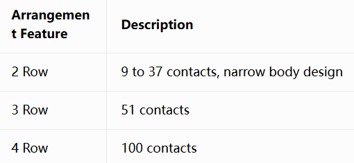
Arrangement vs. Contact Count
M83513 contact arrangements use a 1.27mm grid spacing; more rows accommodate more contacts. Standard contact counts are: 9, 15, 21, 25, 31, 37, 51, and 100.
Arrangement Selection Tips:
Determine the required contact count first, then select the corresponding slash sheet
Two-row (narrow profile) suits space-constrained panel mounting
Multi-row (three-row/four-row) suits applications requiring more signal channels
The same contact count may have multiple arrangements (straight/right-angle) — choose based on mounting orientation
Termination — The “Art of Connection” Between Connector and Cable
Termination determines how the connector establishes electrical connection with wires or PCB. M83513 offers multiple termination options:
3.1 Solder Cup
Wires are soldered directly to the contact’s solder cup. This is the most traditional termination method, suitable for manual assembly and small-batch production.
Applications: Prototype validation, small-batch production, maintenance replacement
3.2 Crimp
Wires are crimped to contacts using specialized tools, forming a gas-tight connection. Crimp contacts are non-removable.
Applications: High-volume production, automated assembly, applications requiring high-reliability gas-tight connections
3.3 PCB Straight Solder
Contacts are soldered directly to the PCB in a vertical orientation. Eliminates wires, saving space.
Applications: Space-constrained scenarios such as aerospace payloads and missile guidance
3.4 PCB Right-Angle Solder
Contacts are soldered to the PCB at a 90° angle, suitable for mounting parallel to the board surface.
Applications: Scenarios where internal chassis layout requires parallel mounting
3.5 Pre-wired Pigtail
Factory-pre-wired with a certain length of cable, ready for direct use.
Applications: Scenarios requiring quick deployment with no on-site termination
Termination Selection Tips:
Field maintenance/replacement needed → Prioritize solder cup or crimp
Extreme space constraints → Prioritize PCB straight solder
High-volume production → Prioritize crimp (most efficient)
Pre-wired pigtail suits “plug-and-play” scenarios
Contact Count — The Connector’s “Capacity”
The contact count is the most intuitive parameter for M83513 selection, as it determines how many signal channels the connector can transmit.
Standard Contact Counts
MIL-C-83513 offers 8 standard contact counts:
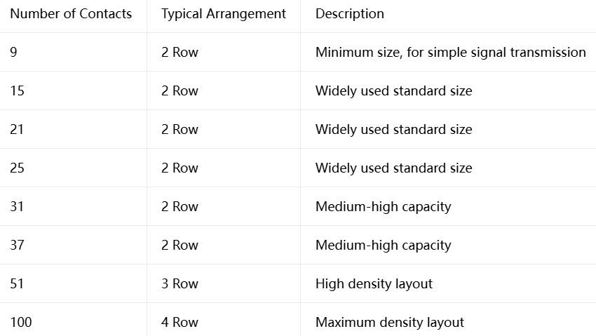
Engineering Considerations for Contact Count Selection
Current needs + margin: Based on current signal requirements, reserve 20%~30% spare contacts for future functional expansion
Balance between shell size and contact count: More contacts mean larger connectors. Choose the smallest contact count that meets your requirements to optimize SWaP
Arrangement restrictions: Not all contact counts support all termination methods and mounting types — verify with the corresponding slash sheet
Five Parameters, One Precise Selection
Shell determines strength and shielding, arrangement determines layout and density, termination determines mounting method, plating determines corrosion resistance and compliance, and contact count determines capacity — together, these five parameters complete a comprehensive M83513 selection.
Master these five parameters, and you can quickly lock onto the one matching model from the 33 MIL-DTL-83513 slash sheets. Whether it’s the miniaturization requirements of aerospace payloads, the high-salt environments of naval equipment, or the RoHS compliance requirements for export to Europe — five parameters, one right choice.
Submit your extreme environment requirements | Get space‑class or deep‑sea selection advice
Recent Posta
Field Maintenance of M83513: How to Quickly Replace Contacts? Our

38999 vs MIL-C-83513: Circular vs Micro-Rectangular Our Products Two Shapes,

Salt Spray Resistance of MIL-C-26482: A Complete Guide to Plating
Get Quote of Connectors