

Field Maintenance of M83513: How to Quickly Replace Contacts?
Field Maintenance of M83513: How to Quickly Replace Contacts? Our
5 Parameters You Must Specify When Procuring 26482: Series / Shell / Plating / Insert Arrangement / Termination
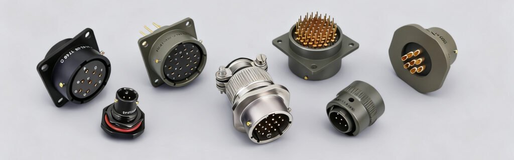
5 Parameters, One Right Choice
MIL-C-26482 (now MIL-DTL-26482) is one of the longest‑serving standards among military circular connectors. Since its inception in the 1950s, it has become a mainstay in aviation, aerospace, ground C4ISR, and industrial applications, thanks to its bayonet quick coupling, medium size, and high‑density contacts.
For procurement professionals, the 26482 selection system can seem complex — series, shell, plating, insert arrangement, termination — five interconnected parameters. This article breaks down each of these five parameters to help you quickly master the 26482 selection logic.
Series I vs Series II
The 26482 consists of two series. They largely overlap in shell sizes and insert arrangements, but differ fundamentally in operating temperature, termination method, and contact maintenance.
Series I
Operating Temperature: -55°C to +125°C
Termination: Solder or front‑release crimp
Contact Maintenance: Removed from the mating face
Series II
Operating Temperature: -55°C to +200°C
Termination: Crimp, rear‑insertable / rear‑release
Contact Maintenance: Removed from the rear without disassembling the entire connector
Selection Tip: If your equipment operates above 125°C (e.g., engine compartments, missile sections) or requires frequent contact replacement, prioritize Series II. If budget is constrained and temperature requirements are moderate, Series I is the classic and reliable choice.
Shell Size (8–24)
The 26482 connector is available in 9 shell sizes, numbered from 08 to 24. The shell size determines the connector’s physical diameter and maximum number of contacts it can accommodate.
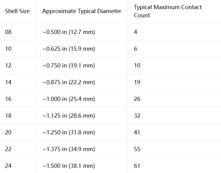
Selection Principle: Larger shell sizes accommodate more contacts but also consume more panel space and add weight. Choose the smallest shell size that meets your contact count requirements to optimize SWaP (Size, Weight, and Power).
Plating (Surface Finish)
Plating determines the connector’s corrosion resistance, conductivity, and environmental adaptability. The 26482 offers multiple plating options:
Olive Drab Cadmium
The most traditional military plating, with excellent corrosion resistance
Good conductivity, providing a reliable EMI grounding path
Electroless Nickel
RoHS compliant, with good corrosion resistance
Uniform coating, suitable for precision thread fits
Black Zinc Nickel
RoHS compliant, with 500‑hour salt spray resistance
Matte black, non‑reflective surface, suitable for stealth / low‑observable platforms
Stainless Steel Passivation
For stainless steel shells, naturally corrosion‑resistant
No additional plating required
Selection Tip: Projects exported to Europe require RoHS compliance — choose electroless nickel, black zinc nickel, or other compliant platings. For domestic non‑export projects, olive drab cadmium remains a reliable choice.
Insert Arrangement (Contact Layout)
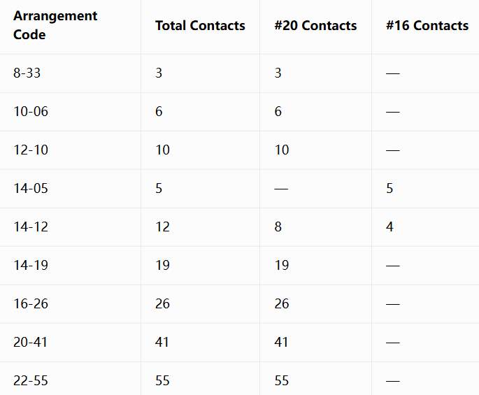
Insert Arrangement determines the number, arrangement pattern, and positions of contacts inside the connector. The 26482 offers 34+ insert arrangement patterns.
The arrangement designation is formatted as “Shell Size‑Arrangement Number” , e.g., 14‑12 means shell size 14, arrangement number 12.

Common Arrangement Examples (Series II):
Contact Sizes and Current Ratings:
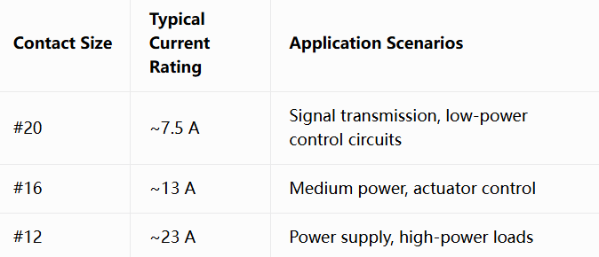
Selection Tip: First tally your signal/power requirements — how many signal lines (#20), how many medium‑power lines (#16), how many power lines (#12) — then find the corresponding arrangement number in the table above.
Termination Method
Termination determines how the connector establishes electrical connection with wires. The 26482 offers the following termination options:
Solder
Wires are soldered directly to the contact’s solder cup
Suitable for manual assembly, small‑batch production, and maintenance replacement
Supported by Series I
Crimp
Wires are crimped to contacts using specialized tools, forming a gas‑tight connection
Suitable for high‑volume production and automated assembly
Series I: Front‑release crimp
Series II: Rear‑insertable / rear‑release crimp
Core Differences in Termination Methods:
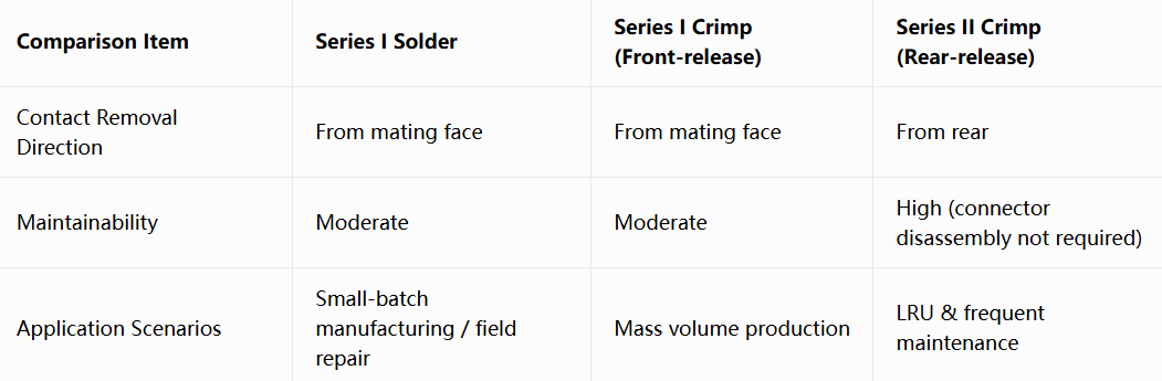
Selection Tip: Field maintenance/replacement needed → prioritize Series II rear‑release crimp; small‑batch or prototype → solder; high‑volume production → crimp (most efficient).
Five Parameters, One Precise Selection
Master these five parameters, and you can quickly lock onto the one matching model from dozens of 26482 arrangements. Whether it’s the stringent requirements of aerospace or the RoHS compliance for export to Europe — five parameters, one right choice.
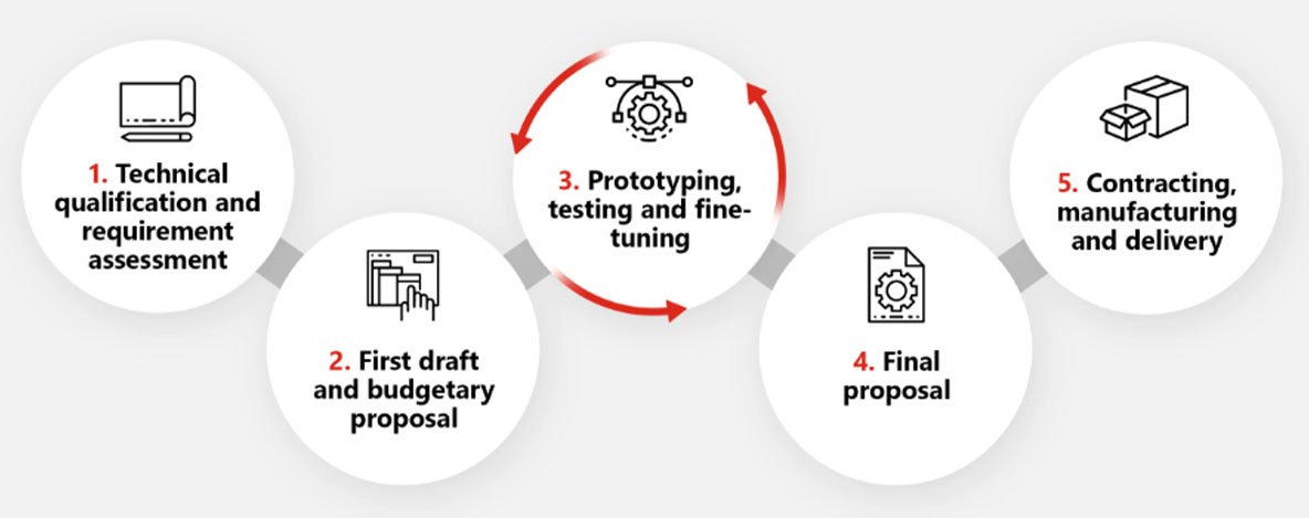
We deliver not just connectors — but a one‑stop solution of “five‑parameter precision matching + European compliance”
Recent Posta
Field Maintenance of M83513: How to Quickly Replace Contacts? Our

38999 vs MIL-C-83513: Circular vs Micro-Rectangular Our Products Two Shapes,

Salt Spray Resistance of MIL-C-26482: A Complete Guide to Plating
Get Quote of Connectors