

Field Maintenance of M83513: How to Quickly Replace Contacts?
Field Maintenance of M83513: How to Quickly Replace Contacts? Our
MIL-C-26482 Complete Guide: From Standard Evolution to Core Parameters

Half a Century of a Connector Standard
MIL-C-26482 is one of the longest-serving standards in the field of military circular connectors. Since its inception in the 1950s, it has become a mainstay in aviation, aerospace, ground C4ISR, and industrial applications, thanks to its bayonet quick coupling, medium size, and high-density contacts. This article provides a complete guide to MIL-C-26482 from four aspects: standard evolution, comparison of the two series, core technical parameters, and selection considerations.
Standard Evolution — From MIL-C-26482 to MIL-DTL-26482
MIL-C-26482 was originally issued in the 1950s as a U.S. Department of Defense military standard for miniature, circular, quick-disconnect, environment-resisting electrical connectors. The standard was designed to meet the demand of military avionics at the time for higher contact density, smaller size, and faster operation speed.
With technological evolution and a shift in military procurement philosophy, the standard underwent significant revisions. The original designation was MIL-C-26482, where “C” stood for “Circular.” Later, the U.S. military transitioned procurement specifications from “dictating how to manufacture” to “specifying which tests must be passed,” and the standard was redesignated MIL-DTL-26482. This transition gave manufacturers greater design innovation freedom while more rigorously defining performance verification requirements.
Although the designation changed, MIL-DTL-26482 retained the core design features of MIL-C-26482: three-point bayonet coupling, a five-key/keyway polarization system, and environmental sealing. The standard remains in widespread use today and is specified for many aviation, aerospace, and ground equipment applications.
The Two Series — Series 1 vs Series 2
The MIL-C-26482 / MIL-DTL-26482 standard defines two series of connectors. They largely overlap in shell sizes and insert arrangements, but differ fundamentally in operating temperature, termination method, and contact maintenance.
Series 1:
Operating temperature: -55°C to +125°C
Termination methods: Solder or front-release crimp
Contact maintenance: Removed from the mating face
Contact type: Removable contacts
Series 2:
Operating temperature: -55°C to +200°C
Termination method: Crimp, rear-insertable / rear-release
Contact maintenance: Removed from the rear without disassembling the entire connector
Contact type: Removable contacts
Intermateability: Series 1 and Series 2 are intermateable when using power contacts; they are not intermateable when using shielded contacts.
Selection advice: If your equipment operates above 125°C (e.g., engine compartments, missile sections) or requires frequent contact replacement, prioritize Series 2. If budget is constrained and temperature requirements are moderate, Series 1 is the classic and reliable choice.
Core Technical Parameters
The core technical parameters of MIL-C-26482 connectors cover shell size, contact arrangement, current-carrying capacity, insulation performance, mechanical life, and environmental adaptability.
Shell Sizes:
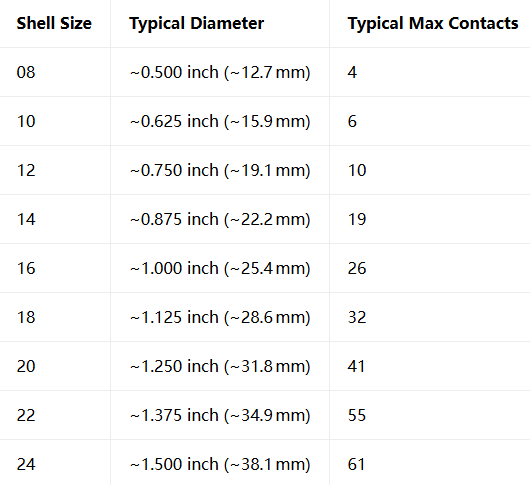
The connector is available in 9 shell sizes, numbered from 08 to 24. The shell size determines the connector’s physical diameter and maximum number of contacts it can accommodate.
Insert Arrangements:
MIL-C-26482 offers over 34 insert arrangement patterns, covering configurations from 2 to 61 contacts. The arrangement designation is formatted as “Shell Size-Arrangement Number” , e.g., 14-12 means shell size 14, arrangement number 12.
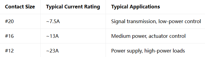
Contact Sizes and Current Ratings:
Insulation Resistance and Dielectric Withstanding Voltage:
Insulation resistance: ≥ 5000 MΩ (at 25°C)
Dielectric withstanding voltage: Up to 1000 VAC (RMS)
Mechanical Life:
Mating cycles: ≥ 500
Environmental Sealing:
MIL-C-26482 connectors offer environmentally sealed and hermetic versions, with protection ratings up to IP66/67 and 500-hour salt spray resistance (depending on plating).
Polarization System:
Features a five-key/keyway polarization system with multiple rotation options such as W, X, Y, Z to prevent misinsertion between different connectors of the same shell size.
Selection Key Points
When procuring MIL-C-26482 connectors, it is recommended to evaluate five key dimensions in the following order:
1. Choose the Series:
Operating temperature ≤125°C → Series 1
Operating temperature >125°C and ≤200°C → Series 2
Frequent contact replacement required → Series 2 (rear-release crimp)
Small-batch or manual assembly → Series 1 (solder)
2. Choose Shell Size:
Determine the shell size based on the required contact count. Choose the smallest shell size that meets your requirements to optimize SWaP (Size, Weight, and Power).
3. Choose Plating:
Export to Europe → Electroless nickel or black zinc nickel (RoHS compliant, cadmium-free)
Domestic non-export projects → Olive drab cadmium (reliable but contains cadmium)
Stainless steel shells → Passivation treatment
4. Choose Arrangement and Termination:
First tally the required signal, medium-power, and power contact counts, then select the corresponding arrangement number. Choose termination based on production volume: solder for small-batch/repair, crimp for high-volume production.
5. Confirm Polarization Keying:
When multiple connectors of the same shell size are installed on the same panel, different polarization rotations (W, X, Y, Z, etc.) must be selected to prevent misinsertion.
Choose Our Connectors

Submit your project requirements (series/shell/plating/arrangement/termination)
Receive selection advice
Recent Posta
Field Maintenance of M83513: How to Quickly Replace Contacts? Our

38999 vs MIL-C-83513: Circular vs Micro-Rectangular Our Products Two Shapes,
Salt Spray Resistance of MIL-C-26482: A Complete Guide to Plating
Get Quote of Connectors