

Field Maintenance of M83513: How to Quickly Replace Contacts?
Field Maintenance of M83513: How to Quickly Replace Contacts? Our
500 Mating Cycles, -55°C to +125°C: Interpreting the Performance Parameters of MIL-C-83513
The Reliability Code Behind the Numbers
In the specification sheets of military connectors, a set of data appears repeatedly: 500 mating cycles, -55°C to +125°C, 3A current rating, 600VAC dielectric withstanding voltage, 8mΩ contact resistance, and 5000MΩ insulation resistance. These are the core performance parameters of MIL-C-83513 (now MIL-DTL-83513) connectors.
These numbers are not filled in arbitrarily; they are the “reliability code” rigorously validated by the U.S. military standard MIL-STD-1344. They define the capability boundaries of this micro-rectangular connector across three dimensions: mechanical life, environmental adaptability, and electrical safety.
This article interprets each core performance parameter of MIL-C-83513, helping you understand the engineering significance behind every number.
500 Mating Cycles — The “Passing Line” of Durability
1.1 What Does 500 Cycles Mean?
The minimum mating life of MIL-C-83513 connectors is 500 cycles.
500 mating cycles may not sound like a lot, but it is a guarantee that after 500 complete mating and unmating cycles, the connector can still pass all electrical and mechanical performance tests.
For most military equipment, 500 cycles are sufficient to cover the entire lifecycle:
Missile guidance systems: only a few mating cycles before launch
Satellite payloads: rarely mated after assembly
Ground C4ISR equipment: dozens of cycles during periodic maintenance
Test and measurement equipment: may require more frequent mating
The 500 cycles of MIL-C-83513 are tested under extreme environmental conditions — high temperature, low temperature, and vibration all at once. The 500 cycles of an industrial connector are measured under ideal laboratory conditions. The “500 cycles” of the two are not the same concept.
1.2 Test Standards for Mating Life
The mating life test of MIL-C-83513 is performed in accordance with MIL-STD-1344. The test requires:
Complete 500 mating cycles at the specified rate
Measure contact resistance after each cycle, ensuring it does not exceed 8mΩ
After 500 cycles, the connector must show no mechanical or electrical defects affecting normal operation
This test ensures that MIL-C-83513 connectors maintain stable electrical performance through repeated use.
1.3 The Battlefield Value of 500 Cycles
For Line Replaceable Units (LRUs) and frequently maintained equipment, 500 mating cycles mean:
Connectors will not prematurely fail due to mating wear
No need to stock large quantities of spare connectors for frequent replacement
From deployment to retirement, a single connector can cover the entire service life
Some manufacturers also offer higher-durability versions to meet the needs of more frequent mating.
-55°C to +125°C — Crossing the 180°C Temperature Extreme
2.1 What Does the 180°C Temperature Difference Mean?
MIL-C-83513 connectors have an operating temperature range of -55°C to +125°C. This means they must maintain stable electrical and mechanical performance across a temperature difference of 180°C.
To understand the significance of this number, consider a comparison:
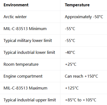
MIL-C-83513’s operating temperature range is approximately 40°C to 80°C wider than that of industrial connectors.
2.2 How Does Temperature Affect Connectors?
Effects of Low Temperature :
Insulation materials become brittle and may crack
Lubricants solidify, increasing mating force
Metals contract, loosening contact fit
Effects of High Temperature :
Insulation materials soften or melt
Contact oxidation accelerates, increasing contact resistance
Shell materials expand thermally, affecting sealing
MIL-C-83513 ensures stable performance across -55°C to +125°C by using high-temperature LCP (Liquid Crystal Polymer) insulators and corrosion-resistant metal shells.
2.3 High-Temperature Versions: Options Beyond 125°C
For extreme applications requiring higher operating temperatures, some manufacturers offer high-temperature versions:
+200°C: Special high-temperature versions
+230°C: F300 series, capable of continuous operation for 500 hours
+260°C: Well-Master™ series
These high-temperature versions feature stainless steel shells, high-temperature LCP insulators, and PTFE-jacketed wires, specifically designed for extreme high-temperature environments such as oil and gas exploration.
Electrical Performance — 3A, 600VAC, 8mΩ, 5000MΩ
The electrical performance of MIL-C-83513 is defined by four core parameters:
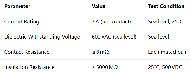
3.1 Current Rating: 3A — “High Power” in a Miniature Size
MIL-C-83513 connectors, with a 1.27mm miniature pitch, can carry 3A of continuous current per contact.
3A may not seem like much, but considering the miniature size of the connector, this is a quite considerable figure. A 51-contact M83513 connector can theoretically carry 153A of total current — in a space the size of a thumbnail.
3.2 Dielectric Withstanding Voltage: 600VAC — The “Firewall” of Insulation Safety
The dielectric withstanding voltage test verifies the connector’s ability to prevent insulation breakdown under high voltage.
MIL-C-83513’s dielectric withstanding voltage at sea level is 600VAC. At 70,000 feet (approximately 21,000 meters) altitude, due to the thin air, the voltage rating drops to 150VAC.
This design ensures electrical safety in high-altitude flight and space environments.
3.3 Contact Resistance: ≤8mΩ — The Guarantee of Lossless Signal Transmission
Contact resistance is a key indicator of connector contact quality. MIL-C-83513 requires the contact resistance of each mated pair to not exceed 8mΩ.
Low contact resistance means:
Low signal transmission loss
Low heat generation
Stable performance over long-term use
The seven independent contact points of the twist pin design are the core guarantee for achieving this low contact resistance.
3.4 Insulation Resistance: ≥5000MΩ — The “Fortress” of Electrical Isolation
Insulation resistance measures the degree of electrical isolation between different contacts and between contacts and the shell.
MIL-C-83513 requires insulation resistance to be no less than 5000MΩ.
5000MΩ means:
No crosstalk between different signals
Electrical isolation maintained even in humid environments
No leakage under high voltage
Mechanical Environmental Adaptability — 50G Shock and 20G Vibration
Beyond the above parameters, MIL-C-83513 also requires passing stringent mechanical environmental tests.
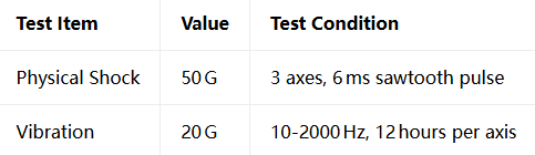
These tests simulate the mechanical stress connectors endure in scenarios such as missile launch, fighter jet flight, and rocket traversing the atmosphere.
50G shock means the connector must withstand an instantaneous force 50 times its own weight.20G vibration means the connector must withstand 20G of continuous vibration across a frequency range of 10Hz to 2000Hz, for 12 hours in each axis.
These tests ensure the signal integrity of MIL-C-83513 connectors under extreme mechanical environments — during testing, signal interruption must not exceed 1 microsecond.
Five Numbers, One Military Commitment
500 mating cycles, -55°C to +125°C, 3A, 600VAC, 8mΩ, and 5000MΩ — these numbers define the performance boundaries of MIL-C-83513 connectors. They are not “paper data” from a laboratory, but “battlefield guarantees” rigorously validated by MIL-STD-1344.
From mechanical life to environmental adaptability, from electrical safety to signal integrity — every parameter answers the same question: Under the most demanding conditions, can this connector work reliably?
MIL-C-83513 gives its answer with these numbers: Yes.
Military-Grade Performance
Submit your project requirements (series/shell/plating/arrangement/termination)
Every performance parameter interpreted above — 500 mating cycles, -55°C to +125°C, 3A, 600VAC, 8mΩ, 5000MΩ, 50G shock, 20G vibration — our product line fully meets all of them
Recent Posta
Field Maintenance of M83513: How to Quickly Replace Contacts? Our

38999 vs MIL-C-83513: Circular vs Micro-Rectangular Our Products Two Shapes,

Salt Spray Resistance of MIL-C-26482: A Complete Guide to Plating
Get Quote of Connectors