

Field Maintenance of M83513: How to Quickly Replace Contacts?
Field Maintenance of M83513: How to Quickly Replace Contacts? Our
Straight vs Right-Angle vs Vertical Mount: A Complete Guide to PCB Mounting Options for MIL-C-83513
Mounting Style Determines the Connector’s “Standing Posture”
When a MIL-C-83513 (Micro-D) connector is soldered onto a printed circuit board (PCB), it does not simply “lie” on the board in any orientation. The relative orientation between the connector and the PCB — known as the mounting style — directly determines the mating direction, space occupancy, soldering process, and maintainability.
In the MIL-C-83513 standard system, PCB mounting styles are primarily defined by Slash Sheets. Common mounting orientations include: straight (vertical mount), right-angle (right-angle mount), and a frequently overlooked but equally important vertical mount with side entry.
This article helps you fully understand the differences among these three PCB mounting styles from four dimensions — structure, soldering process, space occupancy, and application scenarios — and provides clear selection guidance.
Straight Mount (Vertical Mount) — The Most Direct “Standing” Style
1.1 Structural Characteristics
Straight mount, also called vertical mount, means the connector body is perpendicular to the PCB surface. The contacts pass straight down through the plated through-holes of the PCB and are soldered on the back side of the board.
In this mounting style, the mating direction is perpendicular to the PCB surface — the mating plug is inserted or removed vertically from above.
1.2 Corresponding Slash Sheets
In the MIL-C-83513 standard, vertical mount PCB connectors typically correspond to the M83513/22 through M83513/27 slash sheet series.
1.3 Soldering Process
Contacts pass through PCB holes and are wave-soldered or hand-soldered on the back side
Solder joints are on the back of the PCB, connector body on the front
Suitable for through-hole soldering processes
1.4 Space Occupancy Analysis
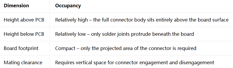
1.5 Applicable Scenarios
Right-Angle Mount — The Low-Profile “Side-Lying” Style
2.1 Structural Characteristics
Right-angle mount means the connector body is parallel to the PCB surface. The contacts bend out from the rear of the connector at a 90° angle and either pass down through PCB holes or are soldered directly to board pads.
In this mounting style, the mating direction is parallel to the PCB surface — the mating plug is inserted or removed horizontally from the side.
2.2 Corresponding Slash Sheets
In the MIL-C-83513 standard, right-angle PCB connectors are divided into two categories:
Narrow-body right-angle: M83513/10 through M83513/15
Standard right-angle: M83513/16 through M83513/21
2.3 Soldering Process
Bent contacts can be through-hole soldered or surface-mounted (SMT) directly to board pads
Solder joints on the front or back of the PCB (depending on design)
Suitable for reflow or wave soldering processes
2.4 Space Occupancy Analysis
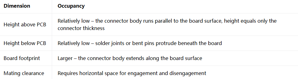
2.5 Application Scenarios
Vertical Mount with Side Entry — The Easily Overlooked “Third Direction”
3.1 Structural Characteristics
“Vertical mount with side entry” is a mounting style between straight and right-angle. The connector body is perpendicular to the PCB surface, but the mating direction is parallel to the PCB surface. In other words, the connector “stands” on the PCB, but the plug is inserted horizontally from the side.
This mounting style is relatively uncommon in practice but offers unique advantages in certain specific scenarios.
3.2 Differences from Straight and Right-Angle
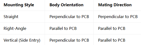
3.3 Applicable Scenarios
Comprehensive Comparison of the Three Mounting Styles
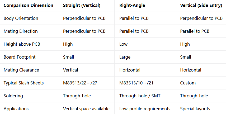
Selection Decision — Four Questions to Help You Choose
Q1: Is vertical height limited?
Yes → Right-Angle Mount
No → Move to next question
Q2: Is the mating direction vertical or horizontal?
Vertical (from above) → Straight (Vertical Mount)
Horizontal (from side) → Move to next question
Q3: Does the connector body need to “stand” to save board area?
Yes → Vertical Mount (Side Entry)
No → Right-Angle Mount
Q4: Is the soldering process through-hole or surface-mount?
Through-hole → Straight or Vertical (Side Entry)
Surface-mount → Right-Angle is more common
Mounting Style Determines the Connector’s “Posture”
Straight, right-angle, and vertical mount with side entry — each of the three PCB mounting styles has its own unique space occupancy characteristics and applicable scenarios. Straight is suitable for applications with ample vertical space, right-angle for low-profile requirements, and vertical mount with side entry provides a third option for special layouts.
The core logic of selection is: first look at space constraints, then at mating direction, and finally at soldering process. Understanding the differences among these three mounting styles allows you to quickly lock onto the slash sheet that best fits your project requirements among the many options in MIL-C-83513.
Configured to Your Needs
Every PCB mounting style described above — straight, right-angle, and vertical mount with side entry — our product line covers all of them
Submit your signal type and data rate requirements | Receive selection advice
Recent Posta
Field Maintenance of M83513: How to Quickly Replace Contacts? Our

38999 vs MIL-C-83513: Circular vs Micro-Rectangular Our Products Two Shapes,

Salt Spray Resistance of MIL-C-26482: A Complete Guide to Plating
Get Quote of Connectors