

Field Maintenance of M83513: How to Quickly Replace Contacts?
Field Maintenance of M83513: How to Quickly Replace Contacts? Our
D38999 Part Number Fully Decoded: Shell Type + Material/Plating + Size + Arrangement — A Selection Guide
A String of Characters, a Set of Codes
When you first see a part number like D38999/20FA35PN, it may look like nothing more than a meaningless string of letters and numbers. But for engineers and procurement professionals, this string is a precise engineering language — it tells you the connector’s shell type, material and plating, shell size, insert arrangement, contact type, and polarization keying.
MIL-DTL-38999 is one of the most widely used standards in military circular connectors. Understanding its part number is equivalent to mastering the “codebook” of this standard. This article breaks down every component of the D38999 part number, helping you read all the information from a string of characters.
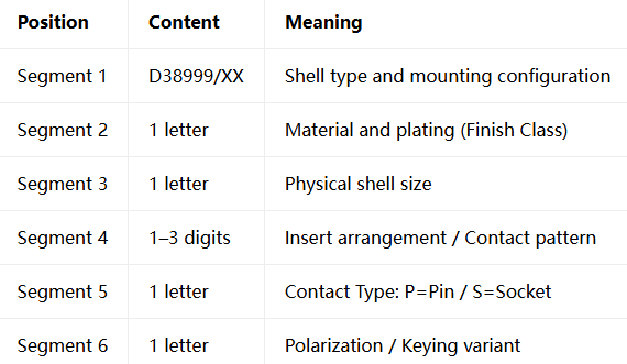
Part Number Structure Overview — A Six-Segment “Engineering Language”
A complete D38999 part number consists of six core segments (excluding the prefix):
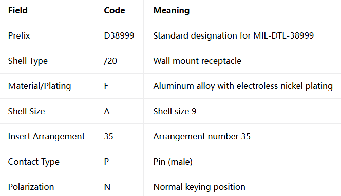
Take D38999/20FA35PN as an example:
Shell Type — The Connector’s “Identity Tag”
The first segment of the part number (D38999/XX) defines the connector’s shell type and mounting method. Different shell types suit different installation scenarios.
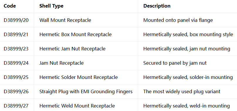
Selection Tip: For panel mounting, choose /20 or /24; for hermetic sealing in space applications, choose /21, /23, /25, or /27; for cable-end connections, choose /26.
Material and Plating — The “Armor” That Determines Environmental Adaptability
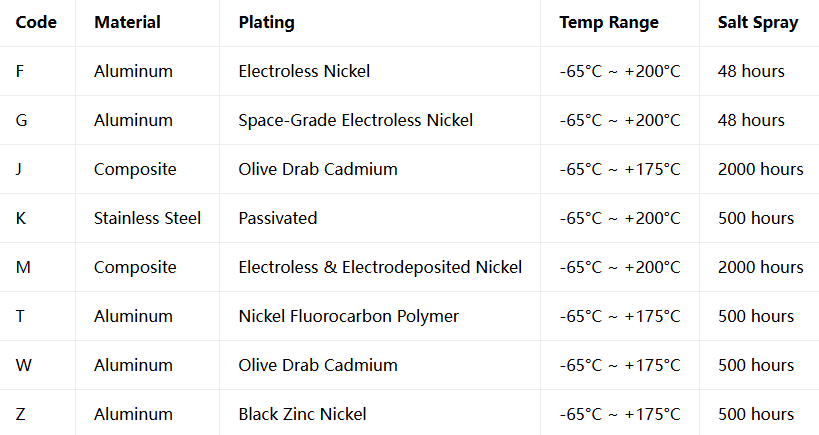
The second segment (one letter) defines the shell material and surface plating. This choice directly affects the connector’s corrosion resistance, operating temperature, and conductivity.
Selection Tip:
Export to Europe → Avoid W/J (contain cadmium, not RoHS compliant); choose F, Z, or other RoHS-compliant platings
Space applications → Choose G (space-grade electroless nickel) or hermetic classes
Highest corrosion resistance → J or M (2,000-hour salt spray)
Firewall/high-safety applications → K (stainless steel passivated)
Important: Although olive drab cadmium (W/J) offers excellent corrosion resistance, it contains the toxic heavy metal cadmium and is not RoHS compliant — special attention is required for export to European markets.
Shell Size — The Connector’s “Size”
The third segment (one letter) defines the shell’s physical size. The shell size determines the connector’s diameter and maximum number of contacts it can accommodate.
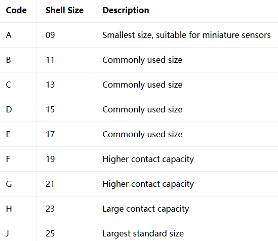
MIL-DTL-38999 shell sizes cover 9 standard sizes from 09 to 25.
Selection Tip: Larger shell sizes accommodate more contacts but also consume more panel space and add weight. Choose the smallest shell size that meets your contact count requirements to optimize SWaP (Size, Weight, and Power).
Insert Arrangement — The Connector’s “Internal Map”
The fourth segment (1-3 digits) defines the arrangement of contacts inside the connector. The arrangement number follows the MIL-STD-1560 standard.
The arrangement number tells you three things:
Common Arrangement Examples:
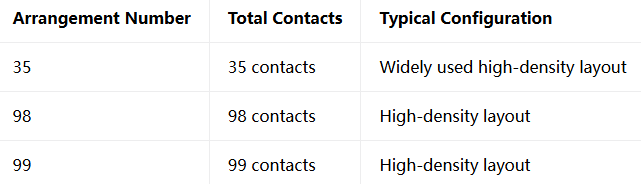
Different shell sizes support different arrangement numbers. For example, shell size D (15) supports 6 different arrangement options. When selecting, first determine the required contact count and contact sizes, then find the supported arrangement numbers for the corresponding shell size.
Contact Sizes and Current Ratings:
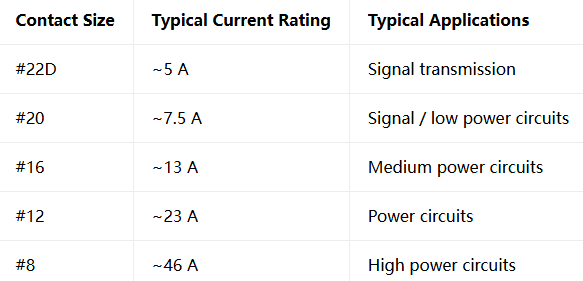
38999 connectors support up to 128 contacts, with contact types including signal, power, coaxial, twinax, quadrax, and fiber optic.
Contact Type and Polarization Keying — The Final “Puzzle Pieces”
Contact Type — Segment 5 (1 letter) :
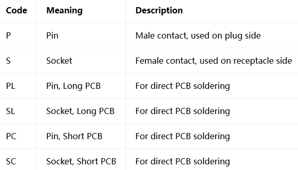
Polarization/Keying — Segment 6 (1 letter) :
Polarization keying determines the rotational alignment of the connector, preventing misinsertion between different connectors with the same shell size and arrangement.
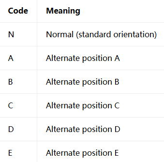
Key Rule: The shell type, shell size, arrangement number, and polarization keying of the plug and receptacle must match exactly for proper mating.
Real-World Decoding — Three Part Number Examples
Example 1: D38999/20FA35PN
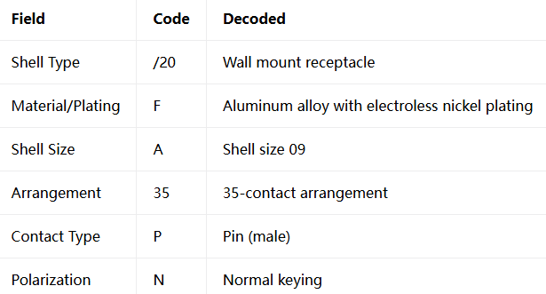
Full Interpretation: MIL-DTL-38999 receptacle with aluminum electroless nickel shell, wall mount flange, shell size 09, 35-contact pin arrangement, normal keying.
Example 2: D38999/26WJ35SN
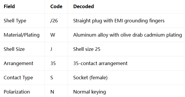
Full Interpretation: MIL-DTL-38999 plug with aluminum olive drab cadmium shell, straight plug with EMI grounding fingers, shell size 25, 35-contact socket arrangement, normal keying.
Example 3: D38999/24ZE99PC
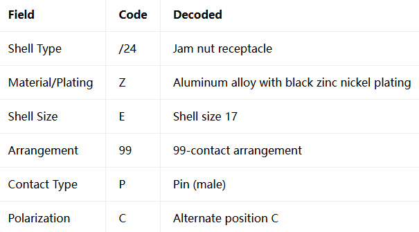
Full Interpretation: MIL-DTL-38999 receptacle with aluminum black zinc nickel plating (RoHS compliant), jam nut mount, shell size 17, 99-contact pin arrangement, keying position C.
The D38999 part number is not a random string of characters — it is a precise engineering coding system. Every letter and every number tells you critical information about the connector — its shape, material, size, arrangement, and polarity.
Master this “codebook,” and you can read all the information from a string of characters, precisely locating the connector configuration you need. Whether you are an engineer, procurement professional, or maintenance technician, understanding the D38999 part number is an essential skill.
Recent Posta
Field Maintenance of M83513: How to Quickly Replace Contacts? Our

38999 vs MIL-C-83513: Circular vs Micro-Rectangular Our Products Two Shapes,

Salt Spray Resistance of MIL-C-26482: A Complete Guide to Plating
Get Quote of Connectors