

Field Maintenance of M83513: How to Quickly Replace Contacts?
Field Maintenance of M83513: How to Quickly Replace Contacts? Our
MIL-C-26482 Complete Guide: From Standard Evolution to Core Parameters
Half a Century of Excellence
In the world of military connectors, few standards have withstood the test of over half a century and remained as widely used as MIL-C-26482. Born in the 1950s, it has become a mainstay in aviation, aerospace, military communications, and industrial applications, thanks to its bayonet quick coupling, compact size, and high reliability.
This article provides a complete guide to MIL-C-26482 from four aspects: standard evolution, comparison of the two series, core parameters, and selection considerations.
Standard Evolution — From MIL-C-26482 to MIL-DTL-26482
MIL-C-26482 was originally issued in the 1950s as a U.S. Department of Defense military standard for miniature, circular, quick-disconnect, environment-resisting electrical connectors. The standard was designed to address the limitation of the earlier MIL-C-5015 connectors, whose smallest contact size (#16) could not meet the demands of high-frequency signal transmission. By introducing #20 size contacts, it achieved miniaturization and improved signal transmission capability. The standard was driven by the U.S. Navy.
With technological evolution and a shift in military procurement philosophy, the standard underwent significant revisions. In 1975, MIL-C-26482G was issued. In 2007, the standard was officially superseded by MIL-DTL-26482H, shifting from a “procurement specification” to a “performance specification”. The standard continued to evolve through subsequent amendments — Amendment 1 in 2009 and Amendment 2 in 2013. In March 2024, MIL-DTL-26482J was issued. The transition from “C” to “DTL” marked a fundamental shift in U.S. military standards — no longer dictating “how to manufacture,” but specifying “what performance requirements must be met” — a transformation that gave manufacturers greater design freedom.
Although the designation changed, MIL-DTL-26482 retained the core design features of MIL-C-26482: three-point bayonet coupling, a five-key/keyway polarization system, and environmental sealing. The standard remains in widespread use today and is specified for many aviation, aerospace, and ground equipment applications.
An important rule: The two series are intermateable when using power contacts; they are NOT intermateable when using shielded contacts.
The Two Series — Series 1 vs Series 2
The MIL-C-26482 / MIL-DTL-26482 standard defines two series of connectors. They largely overlap in shell sizes and insert arrangements, but differ fundamentally in operating temperature, termination method, and contact maintenance.
Series 1:
Operating temperature: -55°C to +125°C
Termination methods: Solder or front-release crimp
Contact maintenance: Removed from the mating face (front)
Contact type: Removable contacts
MS part numbers: MS3110, MS3111, MS3112, MS3114, MS3116 (solder); MS3120, MS3121, MS3122, MS3124, MS3126 (front-release crimp)
Scoop-Proof: Yes
Series 2:
Operating temperature: -55°C to +200°C (some classes rated at 175°C)
Termination method: Crimp, rear-insertable / rear-release
Contact maintenance: Removed from the rear without disassembling the entire connector
Contact type: Removable contacts
MS part numbers: MS3470, MS3471, MS3474, MS3475, MS3476
Scoop-Proof: No
Sealing performance: Improved sealing compared to Series 1
Series 2’s Advantage: The rear-release crimp system of Series 2 is a significant advantage — technicians can insert or remove contacts from the rear of the connector without disassembling the entire assembly, significantly reducing maintenance time. Additionally, Series 2 offers better resistance to hydraulic fluids and lubricating oils.
Core Technical Features
3.1 3-Point Bayonet Coupling
The most core design feature of MIL-C-26482 is its three-point bayonet coupling system.
The receptacle features three stainless steel bayonet pins evenly distributed around the circumference
The plug’s coupling ring has three ramps machined into its inner surface
After pushing the plug into the receptacle, the operator rotates the coupling ring clockwise approximately one-third of a turn (120°)
The bayonet pins slide along the ramps and finally seat into the locking detents at the end
MIL-C-26482’s bayonet coupling provides three independent locking confirmation methods:
Auditory feedback: A clear “click” is heard when fully locked
Tactile feedback: Fingers can feel the sensation of locking into place
Visual feedback: Inspection holes on the coupling ring allow visual confirmation that the bayonet pins are in their locked position
Wave Washer Anti-Loosening: The coupling ring contains a wave washer that continuously applies axial tension, keeping the bayonet pins firmly pressed in the locking detents and preventing self-loosening under severe vibration.
3.2 5-Key/Keyway Polarization
To prevent misinsertion between different connectors of the same shell size, MIL-C-26482 employs a five-key/keyway polarization system. The receptacle features five keyways, and the plug’s coupling ring has five corresponding keys. By varying the relative rotational positions of keys and keyways, multiple polarization configurations can be derived from the same shell size — only a plug and receptacle with perfectly matched keying can mate.
Core Parameters
4.1 Shell Sizes
MIL-C-26482 connectors are available in 8 to 9 shell sizes, numbered from 08 to 24. The shell size determines the connector’s physical diameter and maximum number of contacts it can accommodate.
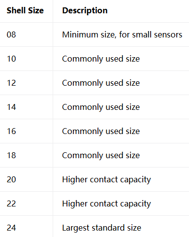
Selection Principle: Choose the smallest shell size that meets your contact count requirements to optimize SWaP (Size, Weight, and Power).
4.2 Insert Arrangements and Contact Count
MIL-C-26482 offers over 60 insert arrangement patterns, covering configurations from 2 to 61 contacts.
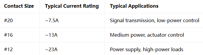
The arrangement designation is formatted as “Shell Size-Arrangement Number” , e.g., 24-61 means shell size 24, 61-contact arrangement.
4.3 Electrical Parameters
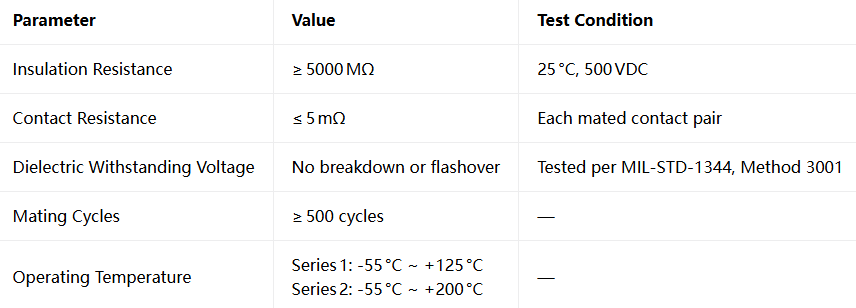
4.4 Environmental Sealing
MIL-C-26482 connectors are designed for environment-resisting applications. Both series offer hermetic socket options. Series 2 offers improved sealing compared to Series 1, with better resistance to hydraulic fluids and lubricating oils. Some models are available in IP66/67 waterproof versions.
Selection Key Points
When procuring MIL-C-26482 connectors, it is recommended to evaluate five key dimensions in the following order:
1. Choose the Series:
Operating temperature ≤125°C → Series 1 (solder or front-release crimp)
Operating temperature >125°C and ≤200°C → Series 2 (rear-release crimp)
Frequent contact replacement required → Series 2 (rear-release crimp, no connector disassembly)
Improved sealing or fluid resistance required → Series 2
2. Choose Termination:
Small-batch/prototype → Solder (Series 1 only)
High-volume production/high-vibration environments → Crimp (Series 1 or 2)
Field maintenance convenience required → Series 2 rear-release crimp
3. Choose Shell Size:
Determine the shell size based on the required contact count (08 to 24). Choose the smallest shell size that meets your requirements.
4. Choose Contact Size:
Choose #20 (~7.5A), #16 (~13A), or #12 (~23A) based on current-carrying requirements.
5. Confirm MS Part Number:
Series 1 solder → MS3110, MS3111, MS3112, MS3114, MS3116
Series 1 front-release crimp → MS3120, MS3121, MS3122, MS3124, MS3126
Series 2 rear-release crimp → MS3470, MS3474, MS3475, MS3476
A Classic Never Goes Out of Style
From the 1950s to the present day, MIL-C-26482 / MIL-DTL-26482 has served for over half a century. Its bayonet coupling design, multiple shell sizes, and diverse contact arrangements make it one of the most classic connector standards in aviation, aerospace, ground C4ISR, and other fields.
Whether you are an engineer, procurement professional, or maintenance technician, understanding the standard evolution, series differences, and core parameters of MIL-C-26482 is the first step to correct selection. Master this knowledge, and you can quickly lock onto the connector configuration that best suits your project requirements.
Classic Standard, Compliance Assured
Every core feature of MIL-C-26482 described above — Series 1 and Series 2, bayonet coupling, wide operating temperature, multiple arrangements — our product line covers all of them
Submit your signal type and data rate requirements | Receive selection advice
Recent Posta
Field Maintenance of M83513: How to Quickly Replace Contacts? Our

38999 vs MIL-C-83513: Circular vs Micro-Rectangular Our Products Two Shapes,

Salt Spray Resistance of MIL-C-26482: A Complete Guide to Plating
Get Quote of Connectors