

Field Maintenance of M83513: How to Quickly Replace Contacts?
Field Maintenance of M83513: How to Quickly Replace Contacts? Our
Military Push-Pull Connector Selection Quick Reference: A Five-Step Method for Standard / Locking Type / Sealing / Shielding / Contact Count
Five Steps, One Right Choice
Push-pull connectors, with their unique push-to-lock, pull-the-sleeve-to-release operating method, have become the preferred choice for quick-disconnect applications in military equipment. From launch vehicle umbilicals to soldier-worn systems, from airborne avionics to ground C4ISR, push-pull connectors are everywhere.
However, for procurement professionals and engineers, the selection of push-pull connectors involves multiple dimensions — standard, locking type, sealing rating, EMI shielding, contact count — each directly affecting the connector’s performance and suitability. This article provides a five-step selection method to help you quickly lock onto the push-pull connector that best fits your project requirements.
Step 1:Choose the Correct “Military Specification ID”
In the military domain, the push-pull connector is not a single model, but a category of connectors defined by its method of operation. Its core standard is MIL-C-81703 (now superseded by SAE-AS81703).
MIL-C-81703 was issued in July 1971, formally titled “Connectors, Electric, Circular, Miniature, Rack and Panel or Push-Pull Coupling, Environment Resisting”. This specification defines three series of environment-resisting, circular, miniature electrical connectors with removable crimp and/or non-removable solder contacts.
Core Differences of the Three Series:
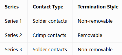
Selection Tip: New designs should use SAE-AS81703 rather than the canceled MIL-C-81703. Push-pull connectors conforming to SAE/AS81703 Series III are also compatible with MIL-DTL-38999 standard inserts, offering greater design flexibility.
Step 2: Choose the Correct “Locking Method”
The locking mechanism of a push-pull connector determines the operating method, mating speed, and vibration resistance. The main types are:
Standard Push-Pull Locking:
This is the most basic push-pull locking method. When the plug is pushed into the receptacle, the spring-loaded locking sleeve is compressed, and internal locking elements (such as balls or latches) expand outward; once fully inserted, the locking sleeve rebounds under spring force, pressing the locking elements into the locking grooves of the receptacle shell, forming a positive mechanical lock. The operator pulls the operating sleeve to unlock and withdraw.
Breakaway:
A special safety design: when the connector is subjected to a predetermined pulling force, it automatically disconnects to prevent damage to equipment or cables. Suitable for emergency egress scenarios such as helmet headsets and weapon interfaces.
Ball Detent Locking:
A common push-pull locking mechanism that achieves locking and unlocking through the radial movement of balls under spring action. Characterized by reliable locking and long mating cycle life.
Locking Feedback:
High-quality push-pull connectors provide audible (click), tactile (locking sensation), and visual (red full-mate indicator stripe) triple feedback. In dark or noisy battlefield environments, this multi-modal feedback is critical.
Selection Tip: Scenarios requiring ultra-fast mating and blind mating → standard push-pull locking; scenarios requiring emergency egress protection → breakaway; scenarios requiring the highest locking reliability → ball detent locking.
Step 3: Choose the Correct “Environmental Protection”
Military push-pull connectors typically need to work reliably in rain, sand, dust, salt spray, and other harsh environments. The sealing rating (IP rating) is the key metric for this capability.
IP Rating Quick Reference:
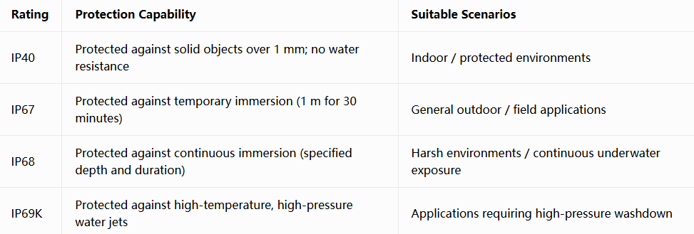
Sealing Features of Military Push-Pull Connectors:
Salt spray resistance: Military push-pull connectors typically offer 500 to 1,000+ hours of salt spray resistance.
Wide operating temperature: Operating temperature range is typically -55°C to +125°C, with some reaching +150°C.
Selection Tip: Indoor applications → IP40; general outdoor → IP67; shipboard/continuous immersion → IP68; high-pressure washdown required → IP69K. Be sure to confirm the specific test depth and duration for IP68.
Step 4: Choose the Correct “Signal Protection”
In the modern battlefield electromagnetic environment, EMI/RFI shielding capability directly affects signal integrity. Push-pull connectors typically achieve shielding through the following methods:
360° Omnidirectional Shielding:
High-quality military push-pull connectors provide 360° EMI/RFI shielding through metal shells, grounding fingers, or shield termination bands for comprehensive electromagnetic protection. Some products also feature integrated EMI/RFI ground springs and shield termination band porches for enhanced shielding.
Shielding Effectiveness:
55dB @ 100MHz: Some push-pull connectors provide 55dB of shielding effectiveness at 100MHz.
Shell-to-shell resistance < 5mΩ: Low shell-to-shell resistance ensures a reliable grounding path.
Selection Tip: Communication equipment, radar front-ends, sensitive electronics → must choose push-pull connectors with 360° EMI shielding; non-sensitive signal transmission → basic shielding or unshielded versions are acceptable.
Step 5: Choose the Correct “Capacity”
Contact count determines how many signals or power lines the connector can carry. Push-pull connectors offer a wide range of contact count options:
Typical Contact Count Ranges:
2 to 7 contacts: Small sensors, simple signal transmission
7 to 37 contacts: Soldier communication equipment, tactical systems
3 to 55 contacts: Standard contact count range for push-pull connectors
2 to 68 contacts: High-density multi-contact configurations
Contact Types:
Push-pull connectors support mixed configurations of multiple contact types:
Signal contacts: Low-voltage signal transmission
Power contacts: Power transmission
Coaxial contacts: RF signals
Fiber optic contacts: High-speed optical communication
High-speed data contacts: USB, Ethernet, etc.
Selection Tip: First tally the required number of signal lines, power lines, and special contacts (coaxial/fiber optic), then select the configuration with the closest contact count that provides some margin. Reserve 20%-30% spare contacts for future expansion.
Five Steps, Selection Made Easy
Standard, locking type, sealing rating, EMI shielding, contact count — these five steps form the complete framework for military push-pull connector selection. Each step corresponds to a clear decision dimension, and each directly affects the connector’s battlefield performance.
Master this five-step method, and you can quickly lock onto the one matching model from the many configurations of push-pull connectors. Whether it’s the lightweighting requirements of soldier systems, the high-salt environments of shipboard equipment, or the EMI shielding requirements of airborne avionics — five steps, one right choice.
Every selection requirement corresponding to each of the five steps above — our product line covers all of them, and all are available with RoHS-compliant plating options (Black Zinc Nickel / Electroless Nickel), ensuring your equipment enters the European market smoothly.
Submit your five-step requirements | Receive selection advice + compliance document templates within 24 hours
Recent Posta
Field Maintenance of M83513: How to Quickly Replace Contacts? Our

38999 vs MIL-C-83513: Circular vs Micro-Rectangular Our Products Two Shapes,

Salt Spray Resistance of MIL-C-26482: A Complete Guide to Plating
Get Quote of Connectors