

Field Maintenance of M83513: How to Quickly Replace Contacts?
Field Maintenance of M83513: How to Quickly Replace Contacts? Our
One “Twist Pin,” Seven Contact Points:
Where Does MIL-C-83513’s High Reliability Come From?
One Contact, Seven Guarantees
In the field of military connectors, MIL-C-83513 (now MIL-DTL-83513) is widely used in mission-critical equipment such as aerospace, missile systems, and radar due to its exceptional reliability. Its secret lies in an unassuming “twist pin” — an elastic contact made of multiple twisted wires that forms seven independent contact points when mated with a rigid socket. This twist pin is the core reason why MIL-C-83513 connectors maintain uninterrupted signal transmission even under severe vibration and shock.
What is a “Twist Pin”? — The Precision Engineering Behind the Name
The twist pin, formally known as the twisted-strand elastic contact, looks like a miniature twist, but its manufacturing process is far more complex than its name suggests.
Structural Breakdown:
Inner Core: 3 pure copper wires
Outer Layer: 7 beryllium copper wires — a material with excellent elasticity and conductivity
Winding Direction: The inner and outer layers are wound in opposite directions
End Treatment: Welded together at both ends to form a robust tip
After the 7 beryllium copper wires are twisted, a bulging “birdcage” structure is formed in the middle of the pin. When inserted into a rigid socket, this bulging portion is compressed while simultaneously twisting and elongating axially. Twist pins are available in three sizes: Centipin (Φ0.95mm) , Micropin (Φ0.63mm) , and Nanopin (Φ0.32mm) , suitable for 1.91mm, 1.27mm, and 0.635mm pitch products respectively.
This precision structural design gives the twist pin a combination of high elasticity, low mating force and excellent vibration resistance — a combination that traditional elastic sockets cannot achieve.
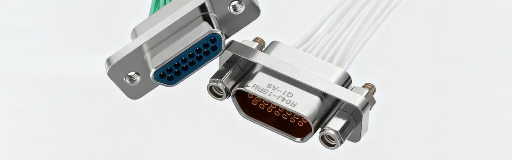
The Manufacturing Process of the Twist Pin — From Metal Wire to Seven Contact Points
The high reliability of the twist pin comes not only from its ingenious design, but also from its stringent manufacturing process.
Manufacturing Process:
Step 1: Twisting — Gold-plated wires are adopted. Via automatic winding technology, inner and outer metal strands are precisely twisted together into a predefined profile through concentric coiling at standard angles.
Step 2: Laser Welding — Both ends of the twist pin are fusion-welded, requiring smooth and strong welds that meet angular design specifications with tolerance class IT12.
Step 3: Heat Treatment — Hardness is controlled to HV340-360, ensuring uniform distribution of inner and outer wires with no loose or broken strands.
Step 4: Gold Plating — The entire contact is plated with 80U“ base and 50U“ gold. This gold plating significantly improves durability, achieving up to 50,000 to 100,000 mating cycles under high-performance conditions.
Seven Contact Points — The Engineering Philosophy of Reliability “Redundancy”
Unlike ordinary connectors with one or two contact points, the twist pin forms seven independent contact points when mated with a rigid socket.
Why “Seven”?
This is not accidental. Seven contact points form a natural redundancy system:
Wear tolerance: Even if individual contact points wear out over prolonged use, the remaining contacts still ensure electrical continuity.
Vibration tolerance: During severe vibration, even if one or two contact points momentarily “bounce” and disconnect, the other contacts maintain the path, preventing signal interruption.
Shock tolerance: Under shock acceleration of up to 50G or even 150G, the seven contact points share the load, ensuring at least some contacts remain engaged.
Additionally, during insertion, the twist pin undergoes not only radial elastic compression but also axial rotational elongation. This unique motion results in much lower insertion and withdrawal forces than traditional rigid pins, while maintaining extremely high contact reliability.
This “multi-point contact” design is the fundamental reason why MIL-C-83513 remains enduringly popular in high-reliability applications.
Twist Pin vs Conventional Stamped Pin — A Clear Distinction
The MIL-DTL-83513 specification defines only minimum performance requirements, giving manufacturers considerable freedom in contact design. Many Micro-D connectors use lower-cost stamped and formed contacts, but independent testing clearly shows that TwistPin contacts provide superior performance in high temperature tolerance, contact retention and crimp strength.
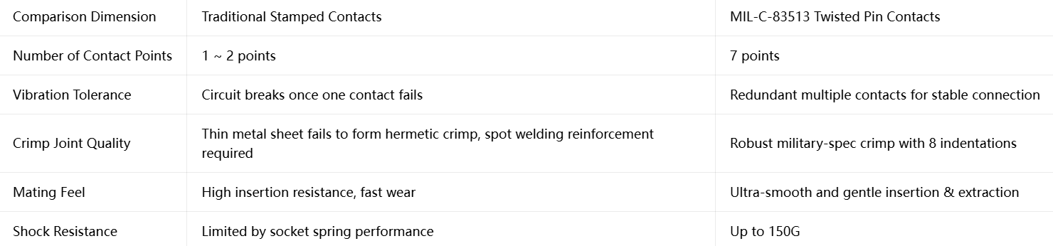
While stamped pins are low-cost and easy to manufacture, their thin sheet metal structure cannot produce a satisfactory gas-tight crimp joint. Micro-D crimp joints are typically concealed with epoxy potting — but the TwistPin, with its superior crimp quality and seven-point contact structure, comprehensively outperforms stamped solutions in reliability.
The MIL-C-83513 Standard System — More Than Just a Twist Pin
The twist pin is the core of MIL-C-83513, but a complete understanding of this standard requires knowledge of its underlying standard system.
Standard Evolution:
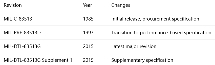
The transition from MIL-C-83513 to MIL-DTL-83513 marked a shift from “how to manufacture” to “what tests must be passed” — a transformation that gave manufacturers greater design innovation freedom, and the twist pin is one of the beneficiaries of this shift.
Testing in Extreme Environments — The “Hardcore” Validation of the Twist Pin
Thermal Shock Test: Rapid temperature cycling between -65°C and +150°C simulates the severe temperature swings satellites experience when transitioning from Earth’s shadow to direct sunlight. Each cycle subjects the connector to thermal stress that can cause delamination or microcracks between different materials. The twist pin’s stranded structure absorbs the stress caused by differential thermal expansion, maintaining connection reliability.
Vibration and Random Vibration Testing: Swept sine and random vibration tests are conducted across 10Hz to 2000Hz, simulating the complex vibration environment of rocket launches and missile flight. Random vibration power spectral density reaches 1.0G²/Hz with total RMS acceleration of 41.7G — enough to cause ordinary connectors to fail within minutes.
Shock Test: Withstands mechanical shock up to 1200m/s² (approximately 122G), simulating the severe overload of missile launch and weapon stage separation. The twist pin’s seven-contact structure plays a decisive role here — even if some contacts momentarily “dislodge,” the remaining contacts maintain continuity.
Salt Spray Corrosion Test: MIL-C-83513 specifies stringent salt spray testing to verify the connector’s corrosion resistance in marine and high-humidity environments. The gold plating plays a critical protective role in this test.
The Miniaturization Advantage of Micro-D — The Engineering Miracle of 1.27mm Pitch
MIL-C-83513 connectors are commonly referred to as “Micro-D” connectors. Their most notable feature is a contact pitch of just 1.27mm — nearly double the density of traditional D-Sub connectors with their 2.76mm pitch.
Contact Count Coverage:
MIL-C-83513 connectors are available in standard configurations of 9, 15, 21, 25, 31, 37, 51, and 100 contacts. The domestic J30J series can be further expanded to 144 contacts.
Shell Material Options:

The high-density of MIL-C-83513 makes it the preferred choice for SWaP (Size, Weight and Power) optimization. In missile guidance sections and satellite payloads, every gram of weight and every cubic centimeter of space is precious — the miniaturization advantage of Micro-D is fully demonstrated here.
Cross-Industry Applications of the Twist Pin
The twist pin’s high reliability has enabled it to “spill over” from military applications to multiple industrial sectors.
Aerospace: Missile guidance systems, satellite communication payloads, radar systems
Military: Fire control systems, smart munitions, phased-array radar, detection equipment
Industrial: Down-hole drilling, medical equipment, telecommunications infrastructure
Commercial Aviation: In-flight entertainment systems, flight control systems
Application Profile: Space-constrained, high-vibration, non-serviceable harsh environments
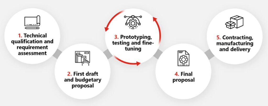
Submit your contact requirements (positions/termination/shell material)
Receive selection advice + technical drawings within 24 hours
Recent Posta
Field Maintenance of M83513: How to Quickly Replace Contacts? Our

38999 vs MIL-C-83513: Circular vs Micro-Rectangular Our Products Two Shapes,

Salt Spray Resistance of MIL-C-26482: A Complete Guide to Plating
Get Quote of Connectors