

Field Maintenance of M83513: How to Quickly Replace Contacts?
Field Maintenance of M83513: How to Quickly Replace Contacts? Our
Push-Pull Connectors in Rack Backplane Blind-Mate Applications: Why Are They More Efficient Than Threaded Connectors?
Rack Backplane — The Invisible “Connection Battlefield”
In modern military electronic equipment, avionics systems, and industrial control cabinets, the rack backplane is the core hub for signal and power distribution. Dozens or even hundreds of modules are inserted into the same rack, and behind each module is a connector that must mate with a receptacle on the backplane. Operators often cannot directly see the mating interface — this is a typical blind-mate scenario.
In this scenario, the choice of connector directly determines assembly efficiency, maintenance speed, and system reliability. Push-pull connectors, with their unique structural design, have become one of the most advantageous solutions for rack backplane blind-mate applications.
This article explains why push-pull connectors are more suitable than threaded connectors for rack backplane blind mating from three dimensions: blind-mate principle, operational efficiency, and engineering advantages.
What Is Rack Backplane Blind Mating?
Rack backplane blind mating refers to the process in which, as a module is inserted into the rack, the connector on the module automatically mates with the receptacle on the backplane, while the operator cannot directly see the mating interface.
The challenges of blind mating are:
Cannot visually align: The operator can only rely on guide features and tactile feel to determine the mating position.
Limited space: The interior of the rack is cramped, and the operator may not be able to reach into the connection area.
Must be completed quickly: During maintenance or module replacement, blind-mate operations must be fast and reliable.
Therefore, blind-mate connectors must have two core capabilities: guidance and tolerance. The connector needs to guide the plug into the correct position through guide features even when not perfectly aligned; at the same time, the connector must allow a certain range of angular and positional deviation to avoid pin damage caused by slight misalignment.
How Do Push-Pull Connectors Achieve Blind Mating?
Push-pull connectors achieve reliable blind-mate capability through three core designs:
1. Guide Features:
The plug and receptacle of push-pull connectors are typically designed with guide chamfers or guide pins. When the plug approaches the receptacle at an angle, the guide features make contact first and “guide” the plug into the correct position. This design allows a certain angular deviation, enabling the operator to complete mating without precise alignment.
2. Polarization Keying:
Push-pull connectors are typically equipped with a multi-key polarization system. The keys on the plug and the keyways on the receptacle must match exactly for mating. In blind-mate scenarios, polarization keying not only prevents misinsertion but also serves as an auxiliary guide — the operator only needs to roughly align the plug with the receptacle, and the keying structure will automatically guide the plug into the correct position.
3. Spring-Loaded Locking:
The locking sleeve of a push-pull connector contains a spring. When the plug is pushed into the receptacle, the locking elements automatically snap into the locking grooves of the receptacle shell under spring force. The operator only needs to push to complete locking — no rotation or tools required. This “push to lock” feature makes blind-mate operation extremely simple.
4. Mating Tolerance:
Some push-pull connectors offer ±0.5mm or even greater mating tolerance. This means that even if there is a certain positional deviation between the module and the backplane, the connector can still mate reliably. This tolerance capability is critical in rack backplane applications — factors such as rack manufacturing tolerances, guide rail precision, and thermal deformation can all cause positional deviation between the module and the backplane.
Why Are They More Efficient Than Threaded Connectors?
The efficiency disadvantages of threaded connectors in rack backplane blind-mate applications are mainly reflected in the following four aspects:
1. Operation Speed:
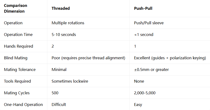
Threaded: Requires multiple rotations (typically 4 or more) to complete locking. In blind-mate scenarios, the operator must first align the threads, then repeatedly rotate, with operation time typically taking 5-10 seconds.
Push-Pull: Only requires pushing in to lock, with operation time typically under 1 second.
In rack backplane applications, the number of modules may be as many as dozens, and the accumulated difference in mating time for each connector translates into an efficiency gap of minutes or even tens of minutes.
2. Hands Required:
Threaded: Typically requires two hands — one to hold the receptacle or module, the other to rotate the plug. In the confined space inside a rack, two-hand operation is extremely difficult.
Push-Pull: One hand is sufficient — hold the module or plug with one hand and push to lock. The other hand can be used to stabilize the module or operate other components.
3. Blind-Mate Capability:
Threaded: Threads require precise alignment before rotation can begin. Without visibility, aligning the threads is extremely difficult. Once the threads are misaligned, forced rotation can cause cross-threading, damaging the connector.
Push-Pull: Guide features and polarization keying allow a certain angular deviation, enabling mating without precise alignment. Even if the plug approaches the receptacle at an angle, the guide features will lead it into the correct position.
4. Tool Requirements:
Threaded: In some applications, lockwire is required to prevent loosening, requiring specialized tools and extra time.
Push-Pull: No tools required. The preload of the wave washer or locking sleeve is already sufficient for vibration resistance and anti-loosening.
5. Mating Cycles:
Threaded: Standard mating life is typically 500 cycles.
Push-Pull: High-quality push-pull connectors can achieve 2,000 to 5,000 mating cycles, far exceeding threaded connectors.
In rack systems requiring frequent maintenance and module replacement, higher mating life means longer service life and lower maintenance costs.
Comparison Overview
Typical Application Scenarios for Rack Backplane Blind Mating
Application scenarios for push-pull connectors in rack backplane blind mating include:
Avionics Racks: Avionics modules are densely arranged in racks and require quick mating during maintenance.
Military Communication Equipment: Communication modules require frequent replacement and upgrades.
Industrial Control Cabinets: Quick maintenance of PLCs, I/O modules, and power modules.
Test and Measurement Equipment: Quick replacement and reconfiguration of test modules.
Ground Support Equipment: Ground testing and maintenance of radar, missile, and other equipment.
Blind-Mate Efficiency Comes from Design
our product line covers all of them, and all are available with RoHS-compliant plating options (Electroless Nickel / Black Zinc Nickel)
Receive selection advice + compliance document templates within 24 hours
Recent Posta
Field Maintenance of M83513: How to Quickly Replace Contacts? Our

38999 vs MIL-C-83513: Circular vs Micro-Rectangular Our Products Two Shapes,

Salt Spray Resistance of MIL-C-26482: A Complete Guide to Plating
Get Quote of Connectors