

Field Maintenance of M83513: How to Quickly Replace Contacts?
Field Maintenance of M83513: How to Quickly Replace Contacts? Our
Shell Sizes 8–24, Contacts 2–61: MIL-C-26482 Selection Quick Reference
MIL-C-26482 (now MIL-DTL-26482) is one of the longest-serving and most widely used military circular connector standards. With its bayonet quick coupling, environmental sealing, and medium contact density, it has established an irreplaceable position in aerospace, naval, ground C4ISR, and high-end industrial equipment.
For engineers or procurement professionals new to the 26482, the biggest challenge often comes from its vast selection system: 9 shell sizes, 2 series, 49 insert arrangements, 3 contact sizes, and 5 polarization rotation options. This article presents a “quick reference” format to help you clarify the 26482 selection logic at a glance.
Series I vs Series II – Choose the Series First, Then the Size
MIL-C-26482 consists of two series. They largely overlap in shell size systems and contact arrangements, but differ fundamentally in operating temperature, contact termination method, and maintenance approach.

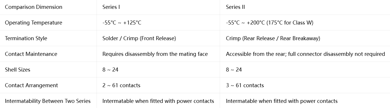
Selection Advice: If your equipment operates above 125°C (e.g., aircraft engine compartments, missile sections) or requires frequent contact replacement (line-replaceable units), prioritize Series II. If budget is constrained and temperature requirements are moderate, Series I is the classic choice.
Shell Size Quick Reference (8–24)
The 26482 connector is available in 9 shell sizes, numbered from 08 to 24. The shell size determines the connector’s physical diameter and maximum number of contacts it can accommodate.
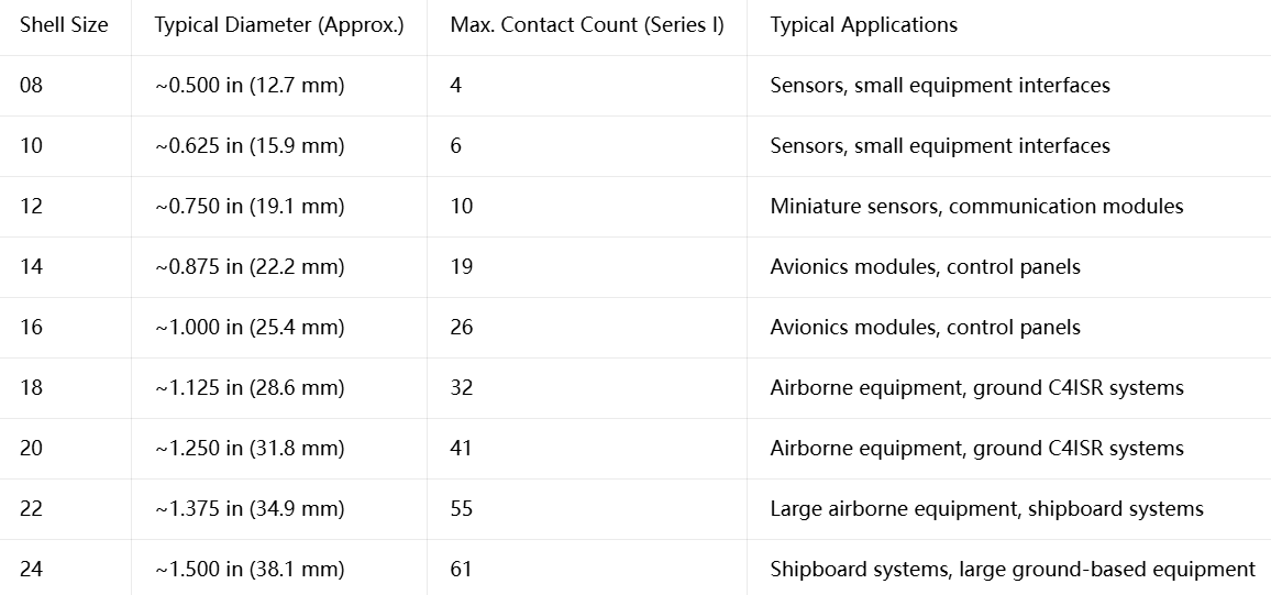
Selection Principle: Larger shell sizes accommodate more contacts but also consume more panel space and add weight. Choose the smallest shell size that meets your contact count requirements to optimize SWaP (Size, Weight and Power).
Contact Arrangement Quick Reference (2–61 Contacts)
The Insert Arrangement is the most critical parameter in 26482 selection. It is determined by the shell size and arrangement number, formatted as “Shell Size-Arrangement Number”, e.g., 14-12 means shell size 14, arrangement number 12.
Below is the quick reference for major contact arrangements common to both Series I and II:
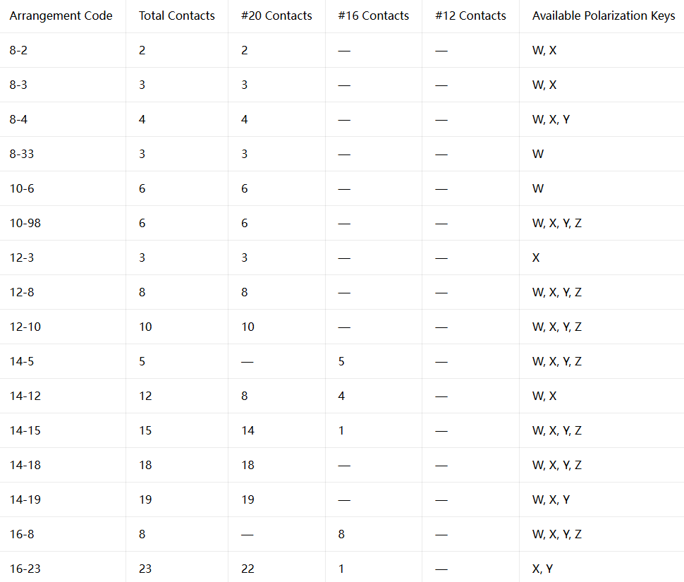
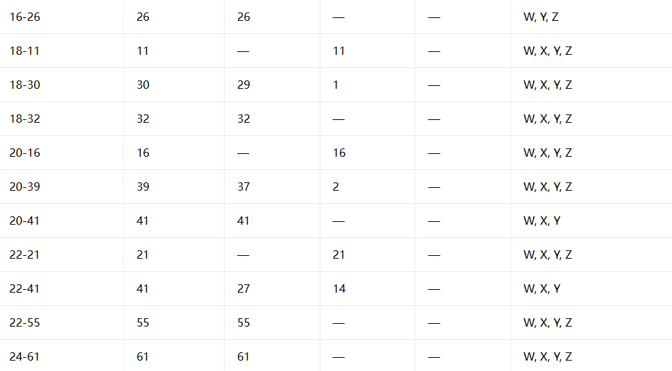
How to Read: Take 14-12 as an example – shell size 14, 12 contacts total, of which 8 are #20 size and 4 are #16 size, with available polarization rotations W and X.
Contact Sizes and Current Carrying Capacity
The 26482 connector primarily uses three contact sizes:
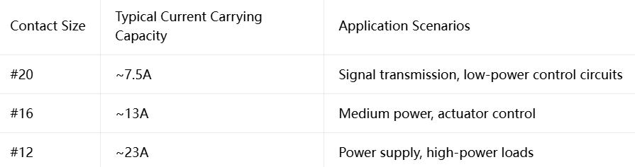
Selection Tip: Before determining shell size and contact arrangement, first tally your signal/power requirements — how many signal lines (#20), how many medium-power lines (#16), how many power lines (#12) — then find the corresponding arrangement number in the table above.
Note: In some arrangements, certain contact positions may be left “blank” or used as shielding contacts. Refer to the specific part drawing for actual usable contact count.
Polarization Rotation – The Key to Preventing Misinsertion
The 26482 connector uses 5 polarization rotation options to prevent misinsertion between different circuits:
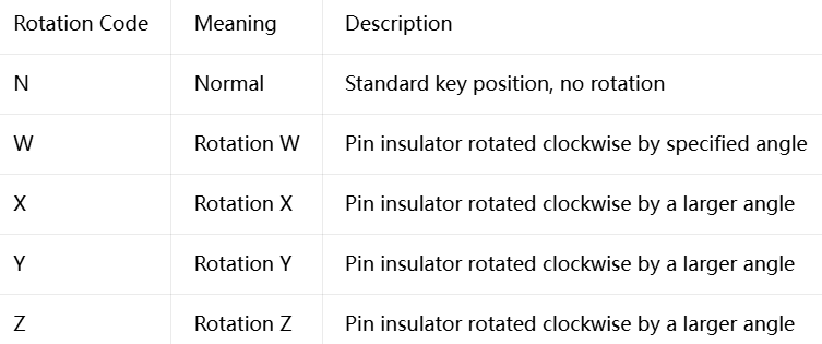
When multiple 26482 connectors of the same shell size are installed on the same panel, different polarization rotations must be used to ensure plugs are not inserted into the wrong receptacles. The “Available Rotations” column in the table above indicates which rotation options are supported for each arrangement.
Key Selection Parameters at a Glance
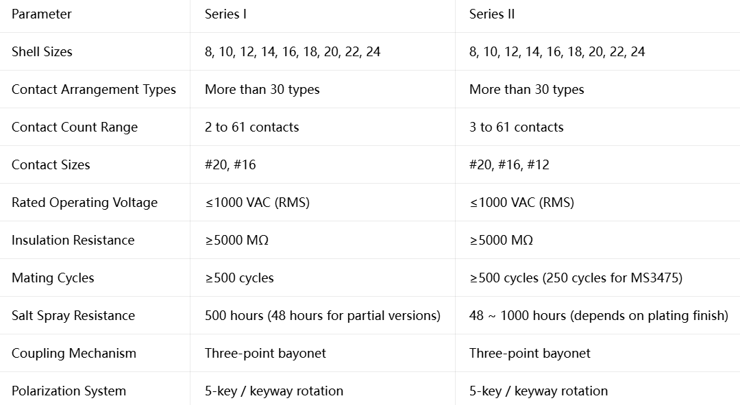
Common Selection Pitfalls
Pitfall #1: “Series I and Series II plugs and receptacles are freely interchangeable”
Reality: The two series are intermateable when using power contacts, but NOT intermateable when using shielded contacts. Always confirm contact type during selection.
Pitfall #2: “Larger shell size means more contacts”
Reality: For the same shell size, more contacts are possible with smaller #20 contacts, fewer with larger #16/#12 contacts. For example, in shell size 14, 14-19 (19×#20) has more contacts than 14-5 (5×#16). Contact count depends on the arrangement number, not solely on shell size.
Pitfall #3: “All arrangements support all polarization rotations”
Reality: Some arrangements support only limited rotation options. For example, 8-2 supports only W and X, not Y and Z. Confirm that your required rotation is available during selection.
Pitfall #4: “500 mating cycles are not enough for the 26482”
Reality: For single-use missiles or spacecraft, 500 cycles are more than sufficient. For ground radios or test interfaces requiring frequent mating, consider Series II (some models support higher durability) or other military series with longer mating life.
The 26482 selection system may seem vast, but once you master the five-step logic of “Series → Arrangement → Size → Rotation → Termination/Plating” , you can quickly lock onto the one matching model from 49 arrangements.
Submit your extreme environment requirements | Get space‑class or deep‑sea selection advice
Recent Posta
Field Maintenance of M83513: How to Quickly Replace Contacts? Our

38999 vs MIL-C-83513: Circular vs Micro-Rectangular Our Products Two Shapes,

Salt Spray Resistance of MIL-C-26482: A Complete Guide to Plating
Get Quote of Connectors