

Field Maintenance of M83513: How to Quickly Replace Contacts?
Field Maintenance of M83513: How to Quickly Replace Contacts? Our
Space Between Extremes: How MIL-C-83513 Bridges Signal Integrity in Outer Space and the Deep Sea
A Connector’s Journey Between Two Extremes
This is the story of a micro‑rectangular connector. It will tell you how a connector with 1.27mm pitch maintains an unbroken signal path through vacuum and high pressure, extreme cold and extreme heat — at both ends of the Earth, and far beyond.
Four hundred kilometers above Earth on the International Space Station, temperatures swing violently between -157°C and +121°C. The vacuum relentlessly pulls moisture and gases from ordinary materials. Cosmic rays penetrate every electronic component every second. Meanwhile, 11,000 meters below sea level in the Mariana Trench, the pressure reaches 1,100 atmospheres, salt spray corrosion attacks every surface, and maintenance is even more impossible than in space.
It sounds like two entirely different worlds. But one connector appears at both extremes — MIL-C-83513.
MIL-C-83513 From “C” to “DTL”: The Identity Evolution of a Connector
1.1 The Birth of a Standard (1985)
In 1985, the U.S. Department of Defense released MIL-C-83513 specifications, setting the standard for polarized shell, microminiature, rectangular electrical connectors. From the very first page, the document is filled with dense technical specifications: operating temperature, contact resistance, dielectric withstanding voltage, vibration rating, salt spray protection, mating life — behind every number lies an extreme definition of “high reliability.”
This standard was groundbreaking because it found an unprecedented balance between “miniaturization” and “high reliability.” Before this, microminiature connectors were either too small to be reliable, or too reliable to be sufficiently small. With MIL-C-83513, designers of missile guidance sections and satellite payloads could finally believe: small can also be powerful.
1.2 From “C” to “DTL”: Twenty Years of Upgrades
In 1994, MIL-C-83513C was released — the final version of the MIL-C-83513 series. Three years later in 1997, the standard was renamed MIL-PRF-83513D, marking a fundamental shift from “procurement specification” to “performance specification” — no longer dictating what materials or processes to use, but specifying what rigorous tests you must pass.
In 2002, the standard was finally upgraded to MIL-DTL-83513, which remains in use today. Revision G was issued in 2015, with subsequent amendments continuing through 2023. A single letter encapsulates the shift from “how to build” to “how to verify.” But what remains consistent is an unchanging promise: never fail when needed most.
1.3 The “Micro-D” Naming
The MIL-C-83513 connector’s mating interface is D‑shaped, hence the name “Micro-D” connector. The “D” refers both to its shape and to its high density — the center‑to‑center spacing between contacts is just 1.27mm, allowing up to 100 contact points in a space the size of a thumbnail. It is precisely this extreme miniaturization that makes it a “space saver” in space and deep‑sea equipment.
The Secret of the Twist Pin – The Miracle of Seven Contact Points
2.1 What Is a Twist Pin?
At the core of every MIL-C-83513 connector lies the component that determines its destiny — the twisted‑strand elastic contact, commonly called the “twist pin.” It is not some high‑tech nanomaterial, but a tiny spring formed by winding metal wires in opposite directions (3 wires in the inner core + 7 or 9 wires in the outer layer). When inserted into a rigid socket, it compresses like a miniature spring, creating seven independent contact points .
2.2 The Engineering Logic of “Seven Contact Points”
Single point contact: once worn or oxidized, the connector fails.
Two point contact: slightly better, but still insufficient redundancy once one point dislodges under vibration.
Seven point contact: even if one or two points temporarily lose connection due to vibration, wear, or corrosion, the remaining five still maintain continuity with the socket, ensuring the signal chain remains intact.
Whether it’s the dozens‑of‑G shock of a missile launch or the vibration from space debris striking a satellite, the redundancy of the seven‑contact mechanism is the core secret to how M83513 survives.
Space – The Triple Challenge of Vacuum, Radiation, and Temperature Extremes
3.1 The Outgassing Crisis in Vacuum Environments
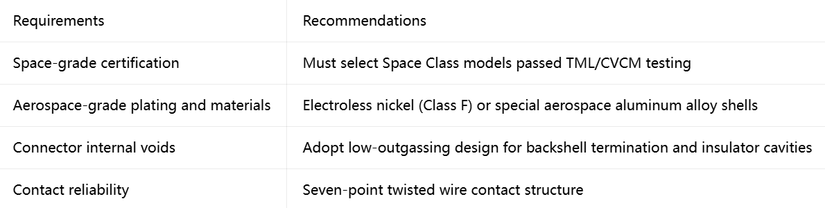
In space, the first challenge a connector faces isn’t “working at below‑zero temperatures.” It’s “not releasing gas” in a vacuum. The interior of a satellite or space station is a sealed system — any trace gas molecules released by materials will float inside the cabin and gradually condense on optical lenses or sensor surfaces, degrading performance or even causing failure. This is known as outgassing.
3.2 “Space‑Class” Standards: NASA’s Stringent Requirements
MIL-DTL-83513 specifically defines a special category — “Space Class” — to address potential outgassing concerns in high‑temperature and vacuum environments. Space‑class connectors must undergo vacuum baking to achieve the following nearly stringent outgassing limits:
These numbers mean: out of 100g of connector material, no more than 1g of volatile substances are released in space — and no more than 0.1g condense on sensitive surfaces. Achieving this level means the connector’s insulator materials have been specially screened and pretreated, and the metal surfaces have undergone thorough cleaning and outgassing.
3.3 Atomic Oxygen Erosion
In low Earth orbit, atomic oxygen is one of the most deadly enemies of materials. It oxidizes metal surfaces and decomposes polymer insulators, drastically degrading connector performance and lifespan. Space‑grade M83513 twist pins undergo dense gold plating, and shells are treated with special passivation processes, using a dense oxide layer or plating to block atomic oxygen attacks.
3.4 Thermal Shock: From -65°C to +200°C
Space‑grade Micro‑D connectors operate across a temperature range of -65°C to +200°C. The connector isn’t just statically exposed to extreme temperatures — it experiences rapid cycles, potentially jumping from -100°C to well over 100°C. Each cycle subjects the connector to thermal stress, which can cause delamination or microcracks between solder joints, insulators, and metal shells. The twist pin’s helical structure absorbs some of the stress caused by this differential thermal expansion, maintaining connection reliability.
3.5 Application Landscape in Space
MIL-C-83513 connectors are widely used in space applications: satellite communication payloads, launch vehicle stage separation systems, signal connections between seekers and inertial measurement units in missile defense systems. Navigation and guidance systems, mission‑critical systems on crewed and uncrewed spacecraft… across all these applications, they have only one mission: no matter how harsh space may be, the signal must get through.
Selection Guide – How to Choose MIL-C-83513 for Extreme Environments
Spacecraft/Space Station Applications
Deep‑Sea/Underwater Equipment Applications
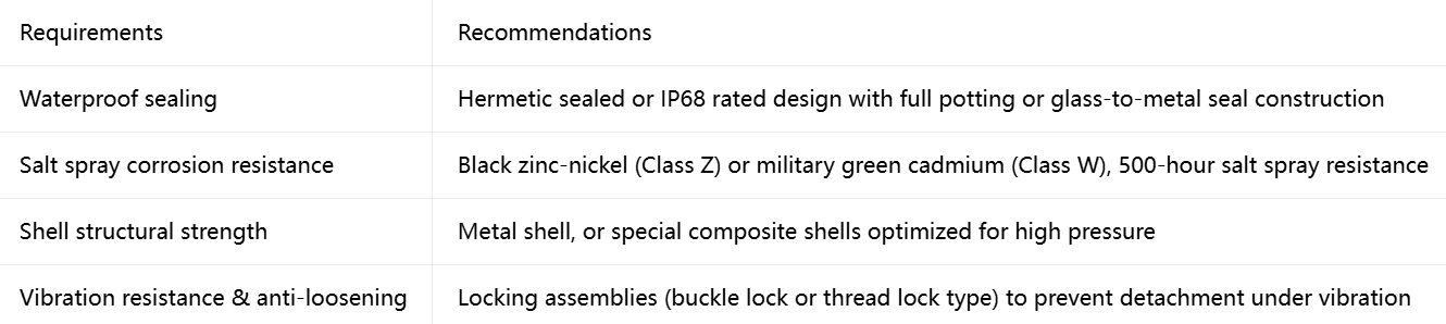
Connection Solutions for Extreme Environments
If your equipment needs to maintain signal integrity in space, or withstand the dual challenges of high pressure and watertight sealing in the deep sea — our product line is already prepared for both extreme worlds.
Submit your extreme environment requirements | Get space‑class or deep‑sea selection advice
Recent Posta
Field Maintenance of M83513: How to Quickly Replace Contacts? Our

38999 vs MIL-C-83513: Circular vs Micro-Rectangular Our Products Two Shapes,

Salt Spray Resistance of MIL-C-26482: A Complete Guide to Plating
Get Quote of Connectors