

Field Maintenance of M83513: How to Quickly Replace Contacts?
Field Maintenance of M83513: How to Quickly Replace Contacts? Our
Vibration and Shock Resistance: How Strong Is the Mechanical Environmental Adaptability of MIL-C-83513?
When Connectors Face “Battlefield-Grade Vibration”
The instantaneous shock of a missile launch, the continuous vibration of a fighter jet in supersonic flight, the violent shaking of a rocket traversing the atmosphere — in these scenarios, the mechanical stress on connectors far exceeds what ordinary industrial equipment ever experiences. A connector that works perfectly in the laboratory may suffer signal interruption within seconds when placed in a real battlefield environment.
MIL-C-83513 (now MIL-DTL-83513) was designed precisely to withstand such extreme mechanical environments. It is not only a representative of “miniaturization,” but also a benchmark for “vibration and shock resistance.” This article will take you through four dimensions — test standards, design principles, data interpretation, and application scenarios — to show just how strong the mechanical environmental adaptability of MIL-C-83513 really is.
Hard Metrics — 50G Shock and 20G Vibration
1.1 What Is “G”?
Before discussing vibration and shock resistance, we first need to understand the unit “G.” One G equals the standard acceleration of gravity at the Earth’s surface, approximately 9.8 m/s². 50G means the connector must withstand an instantaneous force 50 times its own weight.
MIL-C-83513 connectors must pass the following two critical tests:
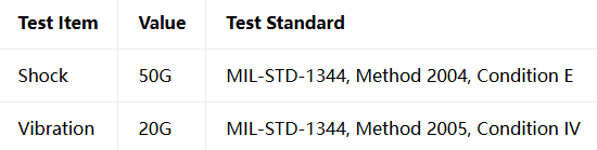
These tests are defined by MIL-STD-1344 (Military Standard — Test Methods for Electrical Connectors) and serve as the “admission ticket” that military connectors must pass.
1.2 Shock Test: What Does 50G Mean?
The shock test simulates the connector’s performance under instantaneous severe impact — such as the overload of a missile launch, the blast wave of an artillery explosion, or the violent jolts encountered during equipment transport.
The shock test for MIL-C-83513 requires applying a 50G, 6-millisecond sawtooth pulse shock in three axes (X, Y, and Z) . Throughout the entire shock process, the connector must not experience signal interruption exceeding 1 microsecond.
What is 1 microsecond? It is one millionth of a second. Under a 50G shock, the connector must maintain signal continuity within one millionth of a second to pass the test.
1.3 Vibration Test: The “Continuous Test” of 20G
Unlike the “instantaneous burst” of shock, the vibration test is a continuous test of the connector.
The vibration test for MIL-C-83513 requires applying 20G vibration across a frequency range of 10Hz to 2000Hz, for 12 hours in each axis. This means the connector must endure 12 hours of continuous vibration in each of three axes — 36 hours total — while maintaining signal continuity without interruption exceeding 1 microsecond.
1.4 Higher Standards: 294m/s² and 735m/s²
Beyond the U.S. military standard requirements of 50G/20G, MIL-C-83513 connectors also perform excellently under even more stringent test conditions:
Vibration: 294 m/s² (approximately 30G), 10Hz to 2000Hz
Shock: 735 m/s² (approximately 75G), 11ms duration
Random Vibration: Power spectral density 0.4G²/Hz, total RMS acceleration 23.1G
These figures show that the actual vibration and shock resistance of MIL-C-83513 far exceeds the minimum standard requirements — it is not “just passing,” but “far exceeding” the mark.
The Design Code — How Does the Twist Pin Withstand Vibration and Shock?
2.1 Seven Contact Points: Redundancy Equals Reliability
MIL-C-83513 connectors feature a unique twisted-strand elastic contact, commonly known as the “twist pin”. It is formed by twisting multiple metal wires together, and a single contact provides seven independent contact points.
Why are seven contact points so important? In vibration and shock environments, a traditional single-point contact connector will lose signal the moment the contact “bounces” off. The twist pin’s seven contact points form a natural redundancy system:
Vibration tolerance: Even if one or two contact points momentarily “bounce” off during severe vibration, the remaining contacts still maintain the path
Shock tolerance: Under 50G or even higher shock, multiple contacts share the load, ensuring at least some contacts remain engaged
Wear tolerance: Even if individual contacts wear out over prolonged use, the remaining contacts still ensure electrical continuity
As one industry expert summarized: “Twist pin contacts provide seven independent contact points, significantly improving electrical performance, durability, and resistance to shock, vibration, and extreme temperatures.”
2.2 Elastic Structure: The “Micro-Spring” That Absorbs Shock
The twist pin’s stranded structure is itself a precision micro-spring system. When impact force acts on the connector, the elastic stranded structure of the twist pin can absorb and disperse the impact energy, rather than transmitting the force directly to the contact interface like a rigid pin.
This design gives the twist pin unique advantages in the following areas:
Absorbing impact energy: The stranded structure can elastically deform to absorb instantaneous shock
Adapting to micro-motion displacement: During vibration, the strands can micro-adjust position to maintain stable contact with the socket
Reducing wear: Elastic contact reduces rigid friction, extending mating life
2.3 Twist Pin vs Stamped and Formed Contacts: A Clear Distinction
Not all connectors conforming to MIL-DTL-83513 use twist pins. Some manufacturers, to reduce costs, use stamped and formed contacts.
But there is a significant gap in vibration and shock resistance between the two:
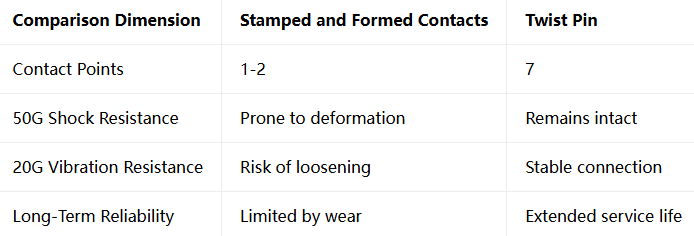
As one industry analysis noted: “Stamped contacts may deform under stress, while twist pins endure shock (50 G’s) and vibration (20 G’s).”
Why Does This Matter? — The Battlefield Value of Mechanical Environmental Adaptability
3.1 Missile Launch: The Test of Instantaneous Overload
The moment a missile is ejected from its launch tube, acceleration can reach dozens of Gs. The 50G shock resistance of MIL-C-83513 connectors ensures that in the initial phase of missile flight — the most critical moment — signals are not interrupted.
3.2 Fighter Jet Flight: The “Endurance Race” of Continuous Vibration
During supersonic flight, a fighter jet’s airframe endures continuous aerodynamic and engine vibration. The 20G, 2000Hz, 36-hour vibration test of MIL-C-83513 simulates precisely this harsh environment lasting for hours.
3.3 Rocket Launch: The Violent Shaking from Zero to Supersonic
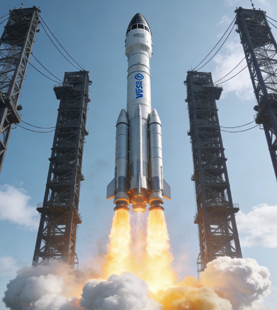
During its passage through the atmosphere, a rocket experiences violent acceleration from zero to several times the speed of sound, while also enduring strong aerodynamic buffeting. The 50G shock and 20G vibration capabilities of MIL-C-83513 ensure that satellite and payload data links remain intact throughout the launch phase.
3.4 Ground Equipment: The Daily Reality of Jolts and Shocks
The jolts of a tank on rough terrain, the shocks of an armored vehicle on off-road drives, the swaying of portable equipment as a soldier runs — these everyday mechanical stresses are equally severe tests for connectors. The mechanical environmental adaptability of MIL-C-83513 makes it equally reliable in these scenarios.
500 Mating Cycles — Not Just Vibration Resistance, But Durability
Beyond vibration and shock resistance, MIL-C-83513 also requires 500 mating cycles. This means that after 500 mating/unmating cycles, the connector must still pass all electrical and mechanical performance tests.
The relationship between 500 mating cycles and vibration/shock resistance is mutually reinforcing:
The elastic structure of the twist pin reduces wear per mating cycle, maintaining good contact even after 500 cycles
The redundancy of seven contact points ensures that even after 500 cycles, enough contact points remain for electrical connection
Rugged shell materials and precision manufacturing ensure the mechanical structure does not deform after 500 cycles
As one supplier datasheet states: “These rugged connectors meet stringent MIL-DTL-83513 reliability standards and are able to maintain integrity under extreme vibration and shock.”
Vibration and Shock Resistance, More Than Just Numbers
Submit your project requirements (series/shell/plating/arrangement/termination)
The story of MIL-C-83513 tells us that a connector born for the battlefield has value far beyond the battlefield. Its miniaturization, high density, high reliability, and wide operating temperature range make it equally outstanding in medical, oil and gas, industrial automation, and test and measurement applications.
Recent Posta
Field Maintenance of M83513: How to Quickly Replace Contacts? Our

38999 vs MIL-C-83513: Circular vs Micro-Rectangular Our Products Two Shapes,

Salt Spray Resistance of MIL-C-26482: A Complete Guide to Plating
Get Quote of Connectors