

Field Maintenance of M83513: How to Quickly Replace Contacts?
Field Maintenance of M83513: How to Quickly Replace Contacts? Our
What Is a Push-Pull Connector? — A Quick Introduction from Working Principle to Military Value
One Motion, Solving One Battlefield Problem
In military equipment, connectors are everywhere — radios on soldiers, sensors on UAVs, avionics modules in fighters, umbilical cables on launch pads. Every connector carries signals or power. But on the battlefield, the way a connector operates is often overlooked — until you need to mate or unmate it in the dark, under fire, with gloves on, using one hand.
The push-pull connector was born precisely to solve this problem. It does not rely on rotation, visual alignment, or two hands — push to lock, pull the sleeve to release.
This article will guide you through a quick introduction to push-pull connectors from five perspectives: standard origin, working principle, core advantages, application scenarios, and selection criteria.
Standard Traceability — The “Military Specification ID” of Push-Pull Connectors
In the military domain, the push-pull connector is not a single model, but a category of connectors defined by its method of operation. Its “military specification ID” is MIL-C-81703 (now superseded by SAE-AS81703).
MIL-C-81703 was issued in July 1971, formally titled “Connectors, Electric, Circular, Miniature, Rack and Panel or Push-Pull Coupling, Environment Resisting”. This specification defines three series of environment-resisting, circular, miniature electrical connectors with removable crimp and/or non-removable solder contacts.
In 1998, MIL-C-81703 was superseded by SAE-AS81703. In 2010, the U.S. military officially issued a notice canceling MIL-C-81703 and all its associated specification sheets, with new designs required to use SAE-AS81703. This transition marked the evolution of push-pull connector standards from military procurement specifications to international aerospace standards.
The three series of MIL-C-81703 / SAE-AS81703 correspond to different contact types and termination methods:
Series 1: Solder contacts, push-pull coupling
Series 2: Crimp contacts, push-pull coupling
Series 3: Solder contacts, push-pull coupling
The associated MS part numbers (such as MS3135, MS3140, etc.) have been replaced by corresponding SAE-AS numbers.
An important historical context: The AS81703 Series 3 push-pull connector emerged to meet the critical operational demands of launch vehicle umbilicals and ground support equipment — requiring rapid, reliable disconnect under time-sensitive and hazardous conditions. It became prominent in the Space Shuttle program and evolved through subsequent launch vehicle programs such as Atlas, Titan, and Delta.
Working Principle — Push to Lock, Pull the Sleeve to Release
The core working principle of a push-pull connector can be summarized in eight words: push to lock, pull the sleeve to release.
Locking Process:
When the plug is pushed into the receptacle, the spring-loaded locking sleeve on the plug housing is compressed by the insertion force, and the internal locking elements (such as balls, latches, or spring rings) expand outward. Once the plug is fully inserted, the locking sleeve rebounds under spring force, pressing the locking elements into the locking grooves of the receptacle shell, forming a positive mechanical lock.
Unlocking Process:
When the operator pulls the operating sleeve on the plug backward, the sleeve compresses the spring, releasing pressure on the locking elements and allowing them to disengage from the locking grooves. The plug can then be freely withdrawn.
Key Design Features:
Spring-loaded locking: The spring inside the locking sleeve continuously applies pressure, ensuring no self-loosening in vibration environments
Blind-mate capability: Guide chamfers and polarization keys on the plug and receptacle guide the plug into the correct position even when not perfectly aligned
Five-key polarization system: Multiple keying options prevent misinsertion between different circuits
Tool-free operation: All operations require no tools
Core Advantages — Why Push-Pull Is the Military’s “Quick-Connect Choice”?
Push-pull connectors have become the military’s “quick-connect choice” due to the following four core advantages:
3.1 Solder Cup
Push-pull connectors are much faster than threaded or bayonet connectors. Push-pull locking ensures reliable mechanical mating and unmating in less than one second. The breakaway function even allows connectors to be mated and unmated in fractions of a second.
Advantage 2: One-Hand Operation
Push-pull connectors allow single-hand operation throughout the process: push to lock and pull to unlock, leaving the other hand free to maintain control of weapons or surroundings. On the battlefield, this means soldiers do not need to set down their weapons to complete connection operations.
Advantage 3: Blind-Mate Capability
In rack backplanes, dark environments, or space-constrained areas, operators often cannot visually align connectors. Push-pull connectors use guide features and polarization key systems to guide the plug into the correct position even when it cannot be seen. TE’s DBAS 9 connector is designed specifically for blind-mate applications.
Advantage 4: High Durability
Push-pull connectors offer significantly higher mating cycle life than threaded or bayonet connectors. Industry-standard products achieve 2,000 to 5,000 mating cycles. This advantage is particularly significant in frequently mated/unmated Line Replaceable Units (LRUs) and test equipment.
Push-Pull vs Threaded vs Bayonet — At a Glance
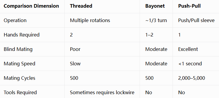
Threaded connectors provide the highest clamping force for long-term high-vibration environments — but at the cost of slow speed and inconvenient operation. Bayonet connectors achieve quick connection with approximately 1/3 turn, but still require rotation and alignment. Push-pull connectors lead in speed, blind mating, one-hand operation, and durability — exactly the four dimensions most needed on the battlefield.
How to Choose a Push-Pull Connector?
In actual selection, it is recommended to evaluate five key dimensions in the following order:
1. Locking Type:
Standard push-pull locking: Push to lock, pull sleeve to release — suitable for most military scenarios
Breakaway: Automatically disconnects when pulled — suitable for emergency egress scenarios
2. Sealing Rating:
IP50: Dust-protected, suitable for protected environments
IP67: Protection against temporary immersion (1m/30 min)
IP68: Protection against continuous immersion — common in military push-pull connectors, with some products achieving IP68 even in unmated condition
3. Contact Count & Contact Types:
Push-pull connectors support a wide range of contact configurations, including signal, power, coaxial, fiber optic, etc.. Contact counts range from 2 to over 100.
4. Environmental Certification:
Military push-pull connectors typically pass MIL-STD-810H environmental testing, covering shock, vibration, extreme temperatures, etc.. Operating temperature range is typically -51°C to +125°C.
5. EMI Shielding:
In high-EMI environments such as radar and communication front-ends, push-pull connectors with 360° EMI/RFI shielding should be selected.
Fast, But Never at the Expense of Reliability
Push-pull connectors have become the military’s “quick-connect choice” not because they sacrifice reliability for speed — on the contrary, they meet military-grade stringent standards across four dimensions: speed, reliability, durability, and environmental adaptability.
They pass MIL-STD-810H shock, vibration, and environmental testing. They offer IP68 sealing, 360° EMI shielding, and 5,000 mating cycles. They allow soldiers to complete connections in the dark, under pressure, with gloves on, using one hand.
From rocket launch pads to soldier combat uniforms, from airborne avionics to UAV sensors — push-pull connectors connect every critical node of the modern battlefield with a crisp “click.”
Recent Posta
Field Maintenance of M83513: How to Quickly Replace Contacts? Our

38999 vs MIL-C-83513: Circular vs Micro-Rectangular Our Products Two Shapes,

Salt Spray Resistance of MIL-C-26482: A Complete Guide to Plating
Get Quote of Connectors